
Related Manuals for Velleman High-Q Velleman-kit K3505


Summary of Contents for Velleman High-Q Velleman-kit K3505
- Page 1 Total solder points: 94 Difficulty level: beginner 1 advanced CAR HEADLIGHT ALARM K3505 ILLUSTRATED ASSEMBLY MANUAL H3505IP-1...
- Page 2 VELLEMAN NV Legen Heirweg 33 9890 Gavere Belgium Europe www.velleman.be www.velleman-kit.com...
-
Page 3: Specifications
Features & Specifications Features: Continuously repeated alarm tone for lights ON (may be disabled) Repeated alarm tone for lights OUT Only 3 wires are required for hook-up Specifications: Supply voltage: 12V battery PCB dimensions: 48 x 57mm (1.9" x 2.2") Recommended housing: WCAH2855... - Page 4 Assembly hints 1. Assembly (Skipping this can lead to troubles ! ) Ok, so we have your attention. These hints will help you to make this project successful. Read them carefully. 1.1 Make sure you have the right tools: • A good quality soldering iron (25-40W) with a small tip.
- Page 5 Assembly hints 1.3 Soldering Hints : 1- Mount the component against the PCB surface and carefully solder the leads 2- Make sure the solder joints are cone-shaped and shiny 3- Trim excess leads as close as possible to the solder joint REMOVE THEM FROM THE TAPE ONE AT A TIME ! DO NOT BLINDLY FOLLOW THE ORDER OF THE COMPONENTS ONTO THE TAPE.
- Page 6 Construction 1. Jumper 4. Resistors 6. Capacitor. R... Between IC1 & IC2 C1 : 100nF (104) 7. Transistor. 2. Diodes. Watch the polarity ! R1 : 47K (4 - 7 - 3 - B) R2 : 47K (4 - 7 - 3 - B) T1 : BC547B D1 : 1N4148 R3 : 47K...
-
Page 7: Electrolytic Capacitors
Construction 9. Electrolytic Capacitors. 11. IC’s. Check the position of Watch the polarity ! the notch! C2 : 22µF C3 : 22µF C4 : 22µF C... C5 : 22µF C6 : 22µF IC1 : CD40106 or eq. C7 : 470µF IC2 : CD4070 or eq 10. - Page 8 Use and connection 12. Use and connection Mount the circuit underneath the dash board and make the following connections: (see Fig. 1.0) Connect the GND connection with the chassis or the battery (-) pole. Connect the L connection with the connection carrying voltage when the lights are turned on. Connect the C connection with the connection carrying voltage when the contact is switched ON.
- Page 9 Use and connection If the alarm should only operate when the driver forgets to turn off the lights, a jumper should be inserted between the J2 connections. K3505 GND L CONTACT WARNING TO TURN LIGHTS OFF ONLY CAR LIGHT Fig. 2.0...
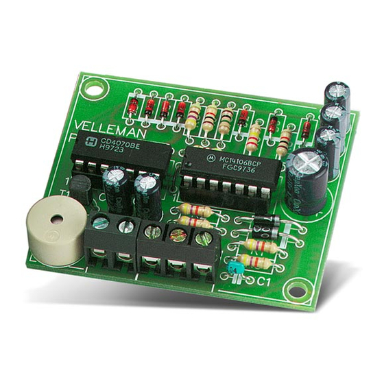
- Page 10 13. PCB layout. VELLEMAN P3505'1 BUZ1...
- Page 11 Diagram 14. Diagram...
- Page 12 Modifications and typographical errors reserved VELLEMAN NV © Velleman Components nv. Legen Heirweg 33, 9890 Gavere H3505IP - 2004 - ED1 Belgium - Europe 5 4 1 0 3 2 9 3 2 7 7 8 1...
Need help?
Do you have a question about the High-Q Velleman-kit K3505 and is the answer not in the manual?
Questions and answers