
Related Manuals for EPH CP4-HW-OT


Summary of Contents for EPH CP4-HW-OT
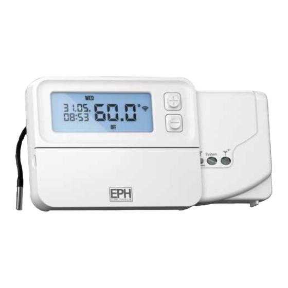
- Page 1 CP4-HW-OT Programmable RF Cylinder Thermostat & Receiver Installation and Operation Guide...
-
Page 2: Table Of Contents
Table of contents RFRP-HW-OT Room Thermostat Installation Instructions Factory Default Settings Frost Protection Specifications How your cylinder thermostat works Mounting of temperature sensor Mounting & Installation RF1A-OT Wireless Receiver Installation Instructions Specifications & Wiring Mounting & Installation RFRP-HW-OT Room Thermostat Operating Instructions LCD Symbol Description Button Description... - Page 3 Programming Modes Adjust the program setting in 5/2 Day mode Copy Function Permanent Override Boost Function Holiday Function Frost Protection Backlight mode selection Battery low warning Frost Protection Replacing the batteries Installer menu PO 1 Operating Mode Normal PO 3 Hysteresis H ON and H OFF PO 4 Calibrate the thermostat PO 5 Frost Protection Exit...
- Page 4 (Continued) RFRP-HW-OT Room Thermostat (Continued) Installer menu - OpenTherm® PO 7 OpenTherm® Information Exit Controlling an OpenTherm® Boiler with multiple CP4-OT/CP4-HW-OT System Architecture RF1A-OT Wireless Receiver Operating Instructions Button / LED Description LED Description To connect the RFRP-HW-OT thermostat to an RF1A-OT receiver...
-
Page 5: Installation Instructions
RFRP-HW-OT Cylinder Thermostat Installation Instructions... -
Page 6: Factory Default Settings
Frost protection is built into this thermostat. It is pre fixed at 5°C and is not adjustable. It will only be activated when the thermostat is in the OFF mode and the cylinder temperature falls below 5°C. RFRP-HW-OT Room Thermostat CP4-HW-OT... -
Page 7: Specifications
130 x 99 x 25mm Temperature sensor: NTC 100K Ohm @ 25˚C External sensor length: 1950mm ± 80mm Temperature indication: ˚C Switching differential: 5˚C Frost protection: Only operational in OFF mode Pollution degree: Pollution degree 2 RFRP-HW-OT Room Thermostat CP4-HW-OT... -
Page 8: How Your Cylinder Thermostat Works
There is only one temperature setpoint which is applied to all programs. The default temperature setpoint is 60˚C. 60˚C is the temperature level required in order to prevent the build up of legionella bacteria. RFRP-HW-OT Room Thermostat CP4-HW-OT... -
Page 9: Mounting Of Temperature Sensor
IN THERMAL POCKET: To ensure accurate control, the temperature sensor should be inserted into the thermal pocket. It is essential that the sensing element is inserted as far as possible. The temperature sensor can be fixed using the provided foil tape. RFRP-HW-OT Room Thermostat CP4-HW-OT... -
Page 10: Mounting & Installation
If the thermostat is used in a way not specified by the manufacturer, its safety may be ƒ impaired. Prior to setting the thermostat, it is necessary to complete all required settings ƒ described in the section. This thermostat can be mounted directly on the wall using the plate included. RFRP-HW-OT Room Thermostat CP4-HW-OT... - Page 11 Lower the flap at the front of the thermostat. There is a battery compartment located below the buttons. Apply downward pressure to remove the cover. Insert the 2 x AA batteries and the thermostat will turn ON. Close the battery compartment. RFRP-HW-OT Room Thermostat CP4-HW-OT...
- Page 12 φ 5...
-
Page 13: Rf1A-Ot Wireless Receiver
RF1A-OT Wireless Receiver Installation Instructions... -
Page 14: Specifications & Wiring
Rated Impulse Voltage: Resistance to voltage surge 2500V as per EN 60730 Internal wiring diagram for RF1A-OT * If mains voltage output is required, terminals L & 2 must be electrically linked. Important: Do not connect Mains Voltage to OpenTherm® terminals. MAINS SUPPLY RF1A-OT Wireless Receiver CP4-HW-OT... -
Page 15: Mounting & Installation
Screw the receiver to the wall with the screws provided. Remove the protective cover on the terminal block. Insert wires into terminal block in accordance with the wiring diagram. Close the cover and tighten the fastening screw. RF1A-OT Wireless Receiver CP4-HW-OT... -
Page 17: Operating Instructions
RFRP-HW-OT Cylinder Thermostat Operating Instructions... -
Page 18: Lcd Symbol Description
LCD Symbol Description Current program Temperature Day of the week Battery low symbol Day / Month Wireless symbol Current Time Heating on symbol (Boost to time) Keypad lock symbol Operating mode RFRP-HW-OT Room Thermostat CP4-HW-OT... -
Page 19: Button Description
Set Date/ Time Automatic mode Set Date / Time Set point increase AUTO TIME Manual mode Holiday mode Set point decrease Off mode Copy function Confirm button COPY Program mode Boost mode Reset button PROG BOOST RFRP-HW-OT Room Thermostat CP4-HW-OT... -
Page 20: Resetting The Thermostat
10 seconds. will appear on the screen. The keypad is now locked. To unlock the keypad, press and hold the buttons for 10 seconds. will disappear from the screen. The keypad is now unlocked. RFRP-HW-OT Room Thermostat CP4-HW-OT... -
Page 21: Setting The Date, Time And Programming Mode
5/2d to 7d or 24h mode. Press the buttons to turn DST (Day Light Saving time) ON or OFF. Press the button or wait 5 seconds and the thermostat will return to AUTO normal operation. RFRP-HW-OT Room Thermostat CP4-HW-OT... -
Page 22: Factory Program Setting
14:00 17:30 19:00 Mon-Fri 08:00 10:00 12:00 14:00 17:30 19:00 Sat-Sun 7 Day 06:30 08:00 12:00 14:00 17:30 19:00 Mon-Fri 08:00 10:00 12:00 14:00 17:30 19:00 Sat-Sun 24 Hour 06:30 08:00 12:00 14:00 17:30 19:00 Everyday RFRP-HW-OT Room Thermostat CP4-HW-OT... -
Page 23: Programming Modes
If 7d mode is selected, you can program each day of the week with 6 individual times. If 24H mode is selected, you can program each day of the week with the same 6 times. RFRP-HW-OT Room Thermostat CP4-HW-OT... -
Page 24: Adjust The Program Setting In 5/2 Day Mode
AUTO While in PROG Mode pressing the button will jump from P1-P2 etc PROG without changing the time. While in PROG Mode pressing the button will jump to the next day TIME (block of days). RFRP-HW-OT Room Thermostat CP4-HW-OT... -
Page 25: Copy Function
Press the button to copy the times and temperatures to that day. Press the button to skip a day. You can copy to multiple days using the button. Press the button when copying has been completed. RFRP-HW-OT Room Thermostat CP4-HW-OT... -
Page 26: Permanent Override
Press or after 5 seconds the thermostat will operate in this permanent override. To cancel permanent override, press the buttton and then press button to return to the automatic mode. AUTO RFRP-HW-OT Room Thermostat CP4-HW-OT... -
Page 27: Boost Function
5 seconds for the boost to activate. ‘BOOST TO’ will now be displayed on the screen with the time that it is activated to displayed above this text. Press the button again to deactivate the boost. BOOST RFRP-HW-OT Room Thermostat CP4-HW-OT... -
Page 28: Holiday Function
Press Press the buttons to adjust the hour. Press The thermostat will now return to the mode it was in before the Holiday settings were entered. To cancel Holiday mode, press the button. RFRP-HW-OT Room Thermostat CP4-HW-OT... -
Page 29: Frost Protection Backlight Mode Selection
OFF or AUTO mode. Press the button. Battery low warning When the batteries are almost empty, the symbol will appear on the screen. The batteries must now be replaced or the unit will shut down. RFRP-HW-OT Room Thermostat CP4-HW-OT... -
Page 30: Frost Protection Replacing The Batteries
Lower the flap at the front of the thermostat. There is a battery compartment located below the buttons. Apply downward pressure to remove the cover. Insert the 2 x AA batteries and the thermostat will turn ON. Close the battery compartment. RFRP-HW-OT Room Thermostat CP4-HW-OT... -
Page 31: Installer Menu
AUTO P0 1: Mode (Normal) P0 3: Hysteresis (differential) P0 4: Calibration P0 5: Frost Protection P0 6: Exit Installer menu OpenTherm® Instructions P0 7: OpenTherm® Information Exit RFRP-HW-OT Room Thermostat CP4-HW-OT... -
Page 32: Po 1 Operating Mode
HON is the fall in temperature – Default – 5.0°C. This will allow a fall of 5°C from the setpoint before the thermostat turns ON again. HOFF is the rise in temperature – Default – 0.0°C. This will allow the temperature to rise 0°C above its setpoint. RFRP-HW-OT Room Thermostat CP4-HW-OT... -
Page 33: Po 4 Calibrate The Thermostat
5˚C. Exit This menu allows the installer to return to the main interface. It is also possible to exit the installer menu by pressing AUTO whilst in the installer menu. RFRP-HW-OT Room Thermostat CP4-HW-OT... -
Page 34: Po 7 Opentherm® Information
PO 7 OpenTherm® Information This menu allows the installer to view information received from the OpenTherm® boiler. It may take a few seconds to load information relating to each parameter. The information that can be shown from the boiler is outlined in the table below. Displayed on screen Description Remark... -
Page 35: Exit
Exit This menu allows the installer to return to the main interface. It is also possible to exit the installer menu by pressing AUTO whilst in the installer menu. RFRP-HW-OT OpenTherm® Instructions... -
Page 36: Controlling An Opentherm® Boiler With Multiple Cp4-Ot/Cp4-Hw-Ot
Controlling an OpenTherm® Boiler with multiple CP4-OT / CP4-HW-OT It is possible to have 6 CP4-OT/ CP4-HW-OT controlling 1 OpenTherm® boiler. To do this it is necessary to make one of the RF1A-OT receivers into a Hub Receiver. This Hub Receiver will receive data from all of the RFRP-OT and RFRP-HW-OT thermostats and relay this information to the boiler via OpenTherm®. - Page 37 Controlling an OpenTherm® Boiler with multiple CP4-OT / CP4-HW-OT (Continued) Identifying if a receiver is a Hub Receiver 1. Press the button. Connect 2. The Hub receiver will flash Green and Red. 3. The Normal receiver will just flash Red.
- Page 38 Controlling an OpenTherm® Boiler with multiple CP4-OT / CP4-HW-OT (Continued) If the installer menu is only showing P01 - P03 then OpenTherm® is not communicating. Check pairing and OpenTherm® wiring. You will see the red light flash on the Hub receiver and see a corresponding flash on the other receivers paired to the Hub Receiver when they are sharing information.
- Page 39 Controlling an OpenTherm® Boiler with multiple CP4-OT / CP4-HW-OT (Continued) Disconnecting the RF1A-OT receiver from Thermostats & other Receivers 1. Press on the Receiver – the red light will flash (red and green Connect light if using a hub receiver) 2.
-
Page 40: System Architecture
System architecture Example A 1 no. Thermostat controlling OT Boiler RFRP-HW-OT Thermostat RF1A-OT Receiver OpenTherm® Boiler RFRP-HW-OT OpenTherm® Instructions... - Page 41 Example B 3 no. Thermostats controlling OT Boiler >> Note: A maximum of 6 thermostats can be used in the system. RFRP-HW-OT Thermostat RFRP-OT Thermostat RFRP-OT Thermostat RF1A-OT Receiver RF1A-OT Hub Receiver RF1A-OT Receiver Motorised Valve Motorised Valve Motorised Valve Auxiliary switch wire from motorised valve OpenTherm®...
-
Page 42: Rf1A-Ot Wireless Receiver
RF1A-OT Wireless Receiver Operating Instructions... -
Page 43: Button / Led Description
Once voltage has been applied this button may Reset button be pressed to initialise the pairing process with the wireless thermostat. Once pressed the red Press to reset the and green LED will begin to flash. receiver RF1A-OT Wireless Receiver CP4-HW-OT... -
Page 44: Led Description
Constant Flash Summary Green LED Red LED RF Communication Error OFF or ON Constant Flash OT Communication Error Constant Flash OFF or ON Normal Operation RF1A ON OFF or Flashing Normal Operation RF1A OFF ON or Flashing RF1A-OT Wireless Receiver CP4-HW-OT... -
Page 45: To Connect The Rfrp-Hw-Ot Thermostat To An Rf1A-Ot Receiver
To connect the RFRP-HW-OT thermostat to an RF1A-OT receiver Please note, If you are installing a CP4-HW-OT the RFRP-HW-OT thermostat & the RF1A-OT receiver will have a pre-established RF connection so it is not necessary to carry out the RF connection process below. -
Page 46: To Disconnect The Rfrp-Hw-Ot Thermostat To An Rf1A-Ot Receiver
Connect If using as a hub receiver, the Red & Green lighs will flash. Press and hold connect for 10 seconds, the receiver will then stop flashing. The RF connection is now cleared. CP4-HW-OT... - Page 47 Notes...
- Page 48 EPH Controls IE technical@ephcontrols.com www.ephcontrols.com/contact-us T +353 21 471 8440 EPH Controls UK technical@ephcontrols.co.uk www.ephcontrols.co.uk/contact-us T +44 1933 322 072...
Need help?
Do you have a question about the CP4-HW-OT and is the answer not in the manual?
Questions and answers