Vertex Standard VX-420 Operating Manual
Ltr
Hide thumbs
Also See for VX-420:
- Service manual (41 pages) ,
- Specifications (2 pages) ,
- Product manual (28 pages)
Advertisement
Quick Links
Download this manual
See also:
Service Manual
VX-420A Series
( LTR )
Operating Manual
C C C C C
& C
& C
& C
& C
& C
ONTROLS
ONTROLS
ONTROLS
ONNECTORS
ONNECTORS
ONNECTORS
ONTROLS
ONTROLS
ONNECTORS
ONNECTORS
LED I
LTR
C
NDICATOR
ONVENTIONAL
Glows Green
System Busy
Monitor on
Blinking Green
---
Busy Channel (or SQL off)
Glows Red
Transmitting
Transmitting
Blinking Red
Battery Voltage is low
Battery Voltage is low
Yellow
Receiving a Selective Call
Receiving a Selective Call
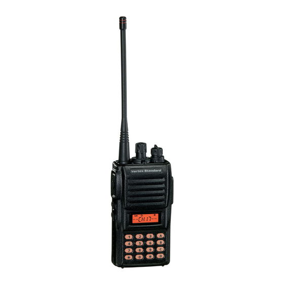
System/Group Selector
Antenna
VOL/PWR Knob
Push To Talk
MIC/SP Jack
( PTT ) Switch
( External Mic/Earphone )
Microphone
Side 1 Switch
Speaker
Side 2 Switch
LCD
16 KEY
Battery Pack Latch
E C 0 7 1 U 1 0 0
SAFETY TRANING INFORMATION
SAFETY TRANING INFORMATION
SAFETY TRANING INFORMATION
SAFETY TRANING INFORMATION
SAFETY TRANING INFORMATION
This Radio has been tested and complies with the Federal Communi-
cations Commission (FCC) RF exposure limits for Occupational Use/
Controlled exposure environment. In addition, it complies with the
following Standards and Guidelines:
FCC 96-326, Guidelines for Evaluating the Environmental Effects
of Radio-Frequency Radiation.
FCC OET Bulletin 65 Edition 97-01 (1997) Supplement C, Evalu-
ating Compliance with FCC Guidelines for Human Exposure to
Radio Frequency Electromagnetic Fields.
ANSI/IEEE C95.1-1992, IEEE Standard for Safety Levels with
Respect to Human Exposure to Radio Frequency Electromagnetic
Fields, 3kHz to 300 GHz.
ANSI/IEEE C95.3-1992, IEEE Recommended Practice for the Mea-
surement of Potentially Hazardous Electromagnetic Fields-RF and
Microwave.
WARNING:This radio generates RF electromagnetic energy
during transmit mode. This radio is designed for and classified
as Occupational Use Only, meaning it must be used only during the
course of employment by individuals aware of the hazards, and the
ways to minimize such hazards. This radio is not intended for use by
the General Population in an uncontrolled environment.
CAUTION:To ensure that your expose to RF electromagnetic
energy is within the FCC allowable limits for occupational use,
always adhere to the following guidelines:
This radio is NOT approved for use by the general population
in an uncontrolled environment. This radio is restricted to oc-
cupational use, work related operations only where the radio
operator must have the knowledge to control its RF exposure
conditions.
When transmitting, hold the radio in a vertical position with its
microphone 1 to 2 inches (2.5 to 5 cm) away from your mouth
and keep the antenna at least 1 inch (2.5cm) away from your
head and body.
B B B B B
Y Y Y Y Y
B B B B B
EFORE
EFORE
EFORE
EFORE
EFORE
OU
OU
OU
OU
OU
EGIN
EGIN
EGIN
EGIN
EGIN
Battery Pack Installation and Removal
To install the battery, hold the transceiver with your left hand, so
your palm is over the speaker and your thumb is on the top of the
belt clip. Insert the battery pack into the battery compartment on
the back of the radio while tilting the Belt Clip outward, then close
the Battery Pack Latch until it locks in place with a "Click."
Insert the Battery Pack
Close the Battery Pack Latch
To remove the battery, turn the radio off and remove any protective
cases. Open the Battery Pack latch on the bottom of the radio, then
slide the battery downward and out from the radio while holding
the Belt Clip.
Caution!
Do not attempt to open any of the rechargeable Ni-Cd packs, as
they could explode if accidentally short-circuited.
Low Battery Indication
As the battery discharges during use, the voltage gradually becomes
lower. When the battery voltage becomes to low, substitute a freshly
charged battery and recharge the depleted pack. The TX/BUSY in-
dicator on the top of the radio will blink red when the battery volt-
age is low.
Avoid recharging Ni-Cd batteries often with little use between
charges, as this can degrade the charge capacity. We recommend
that you carry an extra, fully-charged pack with you so the opera-
tional battery may be used until depletion (this "deep cycling" tech-
nique promotes better long-term battery capacity).
The radio must be used with a maximum operating duty cycle
not exceeding 50 %, in typical Push-to-Talk (PTT) configura-
tions. DO NOT transmit for more than 50 % of total radio use
time (50 % duty cycle). Transmitting more than 50 % of the
time can cause FCC RF exposure compliance requirements to
be exceeded.
The radio is transmitting when the red LED on the top of the
radio is illuminated. You can cause the radio to transmit by
pressing the PTT button or by using the VOX headset, model
VC-25.
DO NOT transmit when the radio is used in Body Worn con-
figuration with the following accessory: belt-clip.
It must be used ONLY for (1) there is a 4 cm distance from the
body during transmitting, (2) monitoring purposes, using the
speaker only and (3) for carrying purposes.
Always use Vertex Standard authorized accessories.
The information listed above provides the user with the information
needed to make him or her aware of RF exposure, and what to do to
assure that this radio operates with the FCC RF exposure limits of this
radio.
Electromagnetic Interference/Compatibility
During transmissions, this radio generates RF energy that can pos-
sibly cause interference with other devices or systems. To avoid
such interference, turn off the radio in areas where signs are posted
to do so.
Do not operate the transmitter in areas that are sensitive to elec-
tromagnetic radiation such as hospitals, health care facilities, air-
craft, and blasting sites.
FCC LICENSE INFORMATION
This radio operates on communications frequencies which are sub-
ject to FCC (Federal Communications Commission) Rules and
Regulations. FCC Rules require that all operators using Private
Land Mobile radio frequencies obtain a radio license before oper-
ating their equipment.
Preliminary Steps
Install a charged battery pack onto the transceiver, as described previ-
ously.
Screw the supplied antenna onto the Antenna jack. Never attempt to
operate this transceiver without an antenna connected.
If you have a Speaker/Microphone, we recommend that it not be con-
nected until you are familiar with the basic operation of the VX-420A
Series ( LTR ) .
Operation Quick Start
Turn the top panel's VOL/PWR knob
clockwise to turn on the radio on.
Turn the top panel's System/Group se-
lector knob to choose the desired operat-
ing channel.
Rotate the VOL/PWR knob to set the vol-
ume level. If no signal is present, press and
hold in the Programmable key assigned
to "NSQL" for more than one second;
background noise will now be heard, and
you may use this to set the VOL/PWR
knob for the desired audio level.
Press and hold in the Programmable
key assigned to "NSQL" for more than
one second (or press the NSQL key twice)
to quiet the noise and resume normal (quiet)
monitoring.
To transmit, monitor the channel and make sure it is clear.
THIS IS AN FCC REQUIREMENT!
To transmit, press and hold in the PTT
switch. Speak into the microphone area of
the front panel grille (lower left-hand cor-
ner) in a normal voice level. To return to
the Receive mode, release the PTT switch.
If a Speaker/Microphone is available, remove the plastic cap and its
two mounting screws from the right side of the transceiver, then insert
the plug from the Speaker/Microphone into the MIC/SP jack; secure
the plug using the screws supplied with the Speaker/Microphone. Hold
the speaker grille up next to your ear while receiving. To transmit, press
the PTT switch on the Speaker/Microphone, just as you would on the
main transceiver's body.
Note:Save the original plastic cap and its mounting screws. They should
be re-installed when not using the Speaker/Microphone.
O O O O O
PERATION
PERATION
PERATION
PERATION
PERATION
Trunking System
Press the PTT switch.
When a channel is available, the TX/BUSY indicator will glow red.
The radio is now transmitting. While holding the PTT switch, speak
into the microphone area of the front panel grille (lower left-hand cor-
ner) in a normal voice level.
If all channels are busy, a continuous tone will be heard from the speaker,
and the "BUSY" notation will appear on the display when the PTT
switch is pressed. Release the PTT switch.
If the radio is out of range during the transmitting attempt, slow beeps
will be heard followed by a continuous tone from the speaker.
D D D D D
I I I I I
& I
& I
& I
& I
& I
ISPLAY
ISPLAY
ISPLAY
ISPLAY
ISPLAY
CONS
CONS
CONS
CONS
CONS
NDICATORS
NDICATORS
NDICATORS
NDICATORS
NDICATORS
"Scan" is activated
"Call" indicator
Low Transmit Power Mode "ON"
Receiver Monitor
"Encryption" is activated
Battery Indicator
RSSI Indicator (four steps)
Home System/Group is selected
8 Character Alpha-numeric Display
Notice !
There are no owner-serviceable parts inside the transceiver. All ser-
vice jobs must be referred to an authorized VERTEX STANDARD
Service Representative. Consult your Authorized VERTEX STAN-
DARD Dealer for installation of optional accessories.
This device complies with Part 15 of the FCC rules. Operation is
subject to the condition that this device does not cause harmful
interference.
Advertisement

Related Manuals for Vertex Standard VX-420


Summary of Contents for Vertex Standard VX-420
- Page 1 8 Character Alpha-numeric Display Notice ! There are no owner-serviceable parts inside the transceiver. All ser- vice jobs must be referred to an authorized VERTEX STANDARD Service Representative. Consult your Authorized VERTEX STAN- DARD Dealer for installation of optional accessories.
- Page 2 These Programmable keys functions can be customized (set to other a higher (or lower) System. functions), via programming by your VERTEX STANDARD dealer, to Once the desired System is reached, rotate the System/Group knob to meet your communications/network requirements. Some features may re- select the desired System/Group within the selected System.
Need help?
Do you have a question about the VX-420 and is the answer not in the manual?
Questions and answers