
Related Manuals for MRC PP-X-575-V2 Series


Summary of Contents for MRC PP-X-575-V2 Series
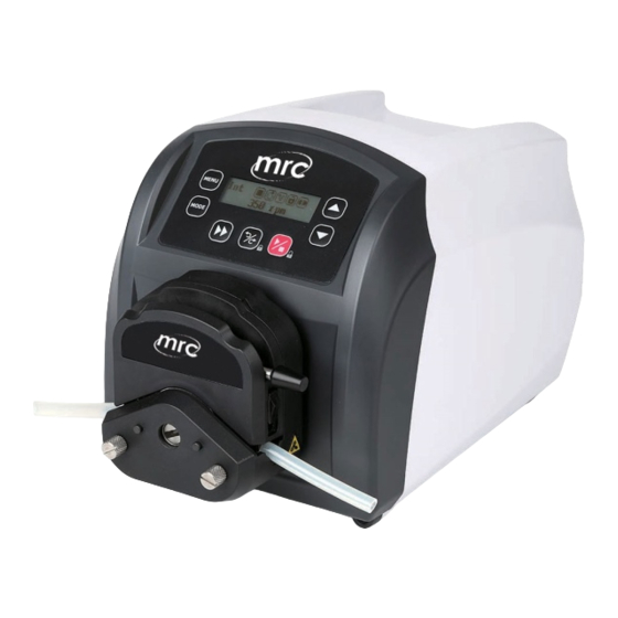
- Page 1 PP-X-575-V2/1600/2900 Series Variable-Speed Peristaltic Pump Operation Manual Hagavish st. Israel 58817 Tel: 972 3 5595252, Fax: 972 3 5594529 mrc@mrclab.com MRC.3.1.24...
- Page 2 Safety Cautions Important information: Be sure to read the instructions carefully before operation! anger: Please use the power supply consistent with that on the nameplate of the machine, otherwise the equipment will be damaged! Do not disassemble the casing and modify the interior of the equipment by yourself, otherwise it will cause faults and even electric shock accidents! When installing and removing the pump tube, please turn off the power...
-
Page 3: Table Of Contents
Contents Description ....................3 Applications ....................3 Functions and Features ................3 Components and Connectors ............... 4 Display Panel and Operation Keypads ............5 Key Board ....................5 LCD Display ..................6 Setup Menu ....................8 System Advanced Parameter Settings ............11 External Control Interface ................ -
Page 4: Description
Description PP-X-575-V2/1600/2900 variable speed peristaltic pump not only has the basic functions of start / stop, speed regulation, full speed, direction, etc., but also is upgraded to LCD ENGLISH display, adding the functions of multi-stage timing operation and reverse. In addition, it can be easily connected and controlled with other equipment through RS485 communication of Modbus protocol : This series of basic variable-speed peristaltic pumps include... -
Page 5: Components And Connectors
RS485 communication, support Modbus communication protocol, and facilitate connection with various control devices WIFI is selected to realize wireless communication and remote control The circuit board is sprayed with three proofing paints to achieve the effect of dust and moisture prevention Strong anti-interference characteristics, wide voltage design, suitable for complex power supply environment ABS plastic shell, beautiful and generous... -
Page 6: Display Panel And Operation Keypads
Display Panel and Operation Keypads LCD Display MENU MODE UP Key DOWN Key Full Speed Direction Key Start/Stop Key Figure 2 Display panel and operation keys Key Board UP key : Value increase key. Press the key once, and add one to the lowest value. Long press this key to increase the value rapidly. -
Page 7: Lcd Display
MODE key : The control mode is switched between internal control, external control, timing, level 1 and level 2. This key is disabled when drive is running. Full speed key: Press this key to switch between the maximum speed and the original state. - Page 8 dispensing, level 1 and level 2. Internal control mode: It is controlled by keys on the panel, and the start and stop are controlled by external pulse signal. External control mode: The speed, external level, signal direction and start stop are controlled by external analog quantity.
-
Page 9: Setup Menu
WIFI did not connect successfully C. Lock status: Displays whether the current is locked. In the locked state, only the start stop on the panel works, and other keys are invalid. In the main interface, long press the direction key to enter the locking state. - Page 10 Figure 4 for details: MENU 1.Run Time Unit MENU 2.Run Time MENU 3.Pause Time Unit MENU 4.Pause Time MENU 5.Cycles MENU 6.Reverse Angle MENU 7.Max Speed MENU 8.Pump No. MENU 9.Beep Setting MENU 10.Language MENU 11.WIFI Rest MENU 12.Contrast MENU 13.Rest Circles Figure 4 Menu setting...
- Page 11 1.Run time unit:In the timing dispensing mode, set the run time unit, and you can set days, hours, minutes and seconds. 2.Run time:In the timing mode, set the run time, with the setting range of 0.1-999 seconds \ minutes \ hours \ days 3.
-
Page 12: System Advanced Parameter Settings
9. Beep setting: Set whether to turn on or off the key prompt tone. 10. Language setting: Switch between Chinese or English. 11.WIFI reset: After resetting WIFI, the mobile app can be rebinding 12. Contrast setting: set the contrast of LCD. 13. - Page 13 System 1.Baud System 2.Stop Bit 3.Parity Mode System 3.Parity Mode 4.Pulse Trigger System 4.Pulse Trigger 5.Level Trigger System 5.Level Trigger 6.Ext Control System 6.Ext Control 7.ACC Time System 7.ACC Time 8.DEC Time System 8.DEC Time 9.Step-Protect System 9.Step-Protect 10.WIFI Set System 10.WIFI Set 11.Time Set...
- Page 14 1. Baud: In the communication mode, set the baud to 4800, 9600, 19200, 38400 (the default is 9600). 2. Stop Bit: In the communication mode, set the size of the stop bit, which can be set to 1 and 2 (the default is 1). 3.
-
Page 15: External Control Interface
External Control Interface DB15 Note Mark Positive end of external analog signal ADC_W input Communication interface, B pole of RS485 Communication interface, A pole of RS485 External voltage input terminal +12V_W CW_W External direction signal input terminal Pulse output External public land Negative end of external analog signal AGND input... -
Page 16: Operation Instructions
Operation Instructions Preparation Work Please check whether all accessories are wrong or damaged according to the packing list. If any problem is found, please contact the manufacturer or distributor in time Carefully read the instruction manual and keep it at hand or in a fixed place for easy reference at any time Install the pump into the embedded square hole or place it on a horizontal table, paste rubber pads at the four corners of the bottom, and keep the... -
Page 17: Power Connection
pump head guide rail, and press the other end into the card, and the tube installation is completed. Power Connection The power supply shall be consistent with the power supply indicated on the nameplate at the rear of the chassis. Plug the included switching power supply into the power socket on the back of the drive. -
Page 18: Internal Control Mode
Internal Control Mode The operation of the pump is controlled by the keys on the front panel of the pump. Turn on the power switch, LCD display and enter the main interface Press key to switch the mode to the internal control mode, as shown in the following figure. -
Page 19: External Control Mode
External Control Mode The speed is controlled by the external input mode analog quantity, and the start/ stop and direction are controlled by the external level. Control panel keys do not work. When the power is cut off, connect the circuit according to the following wiring Figure 9 and 10 and connect the DB15 interface to the back interface of the pump CW_W... -
Page 20: Timing Dispensing Mode
Turn on the power switch, LCD display and enter the main interface key to switch the mode to external control mode, as shown Press in the following figure. 0.0rpm Voltage mode 0-5V/0- Ext I 0.0rpm Current mode 4-20mA Figure 8 External control mode Close external RS_ W switch, turn on the analog power supply, and the pump speed changes with the change of analog. - Page 21 Time 32.5rpm Stop State Time 32.5rpm 1.2s 4 Running state Current run / Interval time Current Completion times Figure 12 Timing dispensing mode Press key to enter the parameter setting interface Set the timing unit, run time, pause time and cycle times respectively Return to the main interface Running Stop...
-
Page 22: Level 1 (Original Foot Switch) Mode
Press key to adjust the rotation direction Press key to run the setting process During operation, press the start / stop key to stop the process In the timing dispensing mode, the start can also be started with the foot switch During operation, the run time or pause time and the number of runs are displayed. -
Page 23: Level 2 Mode
RS_W Figure 16 Wiring diagram of internal 12V power supply under level 1 mode Turn on the power switch and the LCD will display Press key to switch to foot switch mode, as the following figure Lev1 32.5rpm Figure 17 Level 1 mode Press key to adjust the rotation direction Press... - Page 24 CW_W RS_W VCC-W DC5V/12V/24V Figure 18 Wiring diagram of external power supply under level 2 mode CW_W RS_W Figure 19 Wiring diagram of internal 12V power supply under level 2 mode Turn on the power switch and the LCD will display ...
-
Page 25: Communication Mode
Lev2 32.5rpm Figure 17 Level mode Press key to adjust the speed to be set Close external RS_ W switch, the pump operates according to the set speed. Disconnect the external RS_ W switch, the pump stops running. Disconnect CW_ W switch, the pump runs clockwise. Close CW_ W switch, the pump runs counterclockwise. - Page 26 Figure 22 Wiring diagram of internal 12V power supply for communication Turn on the power switch and the LCD will display Press to switch the mode to internal control mode or timing mode Communication 32.5rpm not connected Communication 32.5rpm is normal Figure 20 Communication mode Control various functions of the pump through communication ...
-
Page 27: Speed Setting
C l ick the "+" button of the motor in the upper right corner of the home page of MRC cloud control, select the WI-FI distribution network to add a device, the app will automatically read the current WI-FI, manually enter the Wi-Fi password, click the "link"... -
Page 28: Malfunction And Maintenance
32.5rpm Figure 22 WIFI is connected Malfunction and Maintenance Repair and After-sales This product is guaranteed free of charge for one year (If it is damaged due to improper operation of the user, the company is responsible for the warranty, but the maintenance fee shall be charged) If maintenance is carried out beyond the free warranty period, only material and labor costs and maintenance fees shall be charged. - Page 29 1. Check whether the indicator light of the drive board is on 2. Check whether the connecting wire Motor does not between the motor and the drive board Hardware rotate is in good condition 3. Check whether the connecting line between the drive board and the main control board is in good condition The motor...
-
Page 30: Dimension
Dimension Figure 23 Dimension Naming Rule Driver mode Pump Type Speed Flow Rate Version B (stepper motor) D(fixed speed) 05(50RPM) Q(micro flow W(brushless S(variable- Function 08(80RPM) IP Grade rate) motor) Number speed) 10 (150RPM)* Default: T(laboratory) J(AC motor) L(intelligent IP31 30(350RPM )... -
Page 31: Technical Parameter
Technical Parameter PP-X-575-V2 Technical parameter Main function Suitable Pump YZ15,YZ25,YT15,YT25,DG6,DG10,DT10-18, Heads DT10-28 Control the speed, direction, start and stop, full speed, Key functions working mode and other parameters. External control The external control signal controls the start, stop and function direction, and the analog quantity regulates the speed Communication RS485 communication, support Modbus Protocol. - Page 32 PP-X-1600 Technical parameter Main function Suitable Pump YZ15,YZ25, YT15,YT25 Heads Control the speed, direction, start and stop, full speed, Key functions working mode and other parameters. External control The external control signal controls the start, stop and function direction, and the analog quantity regulates the speed Communication RS485 communication, support Modbus Protocol.
- Page 33 PP-X-2900 Technical parameter Main function Suitable Pump YZ15、YZ25, YT15,YT25 Heads Control the speed, direction, start and stop, full speed, Key functions working mode and other parameters. External control The external control signal controls the start, stop and function direction, and the analog quantity regulates the speed Communication RS485 communication, support Modbus Protocol.
- Page 34 Refer to table for pump head and tube applicable to peristaltic pump driver and flow parameters. Single Driver Suitable pump Number of Suitable tube(mm) channel flow model heads channels (mL/min) wall thickness 0.8~ DG6-1(6 rollers) 0.00016~26 1,ID≤2.4 DG10-1(10 wall thickness 0.8~ 0.00011~20 rollers) 1,ID≤2.4...
-
Page 35: Input And Output Performance Of External Control Port
Input and Output Performance of External Control Port Input switching value or OC door specification Project Parameter VCC_W VCC_W 820Ω Principle of input Signal In interface Single channel signal input 5.5mA<I <15mA ON current Single channel signal input <1.5mA OFF current Switching value (closed, open) or Signal input mode NPN Transistor OC gate... - Page 36 Input analog specification Project Parameter VCC_W VCC_W Principle of input 5.1KΩ Signal Out interface Mode of output NPN Transistor OC gate with internal pull-up Mode of isolation Photoelectric isolation Input analog specification Project Parameter ADC_W Principle of interface AGND AGND AGND 0-5V R1=4KΩ...
- Page 37 Internal output power specification Project Parameter Output voltage DC12V ±1V Allowable output <130mA current External input power specification Project Parameter Allowable input DC5-25V voltage Allowable output >350mA current...
-
Page 38: Version History
Version History Date Version Change 2022-4-20 V1.0 Initial release version...
Need help?
Do you have a question about the PP-X-575-V2 Series and is the answer not in the manual?
Questions and answers