Table of Contents
Advertisement
Quick Links
Advertisement
Table of Contents

Related Manuals for Foster 2998100

Summary of Contents for Foster 2998100
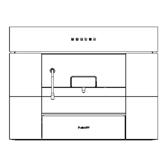
- Page 1 SERVICE MANUAL – Coffee Machine mod. 2998100 - 2998600 Page 1 of 18...
- Page 2 SERVICE MANUAL – Coffee Machine mod. 2998100 - 2998600 INDEX 1) SAFETY 2) SCOPE OF THIS MANUAL 3) DIMENSIONS 4) HYDRAULIC SCHEME 5) ELECTRICAL SCHEME 6) STRUCTURE 1) General access 2) Access to complete coffee unit 7) FAST-ON CONNECTIONS 8) STEAM ADJUSTMENT 9) FUSE REPLACEMENT 10) SAFETY THERMOSTATS RESET 11) KEYBOARD REPLACEMENT 12) POD-DRAWER REMOVAL Page 2 of 18...
-
Page 3: Scope Of This Manual
SERVICE MANUAL – Coffee Machine mod. 2998100 - 2998600 A. SAFETY Prior to accessing to internal components and in general prior to intervening on the appliance at all, make sure that the power cord has been disconnected from the mains and that the hot parts have cooled down. When necessary, and anyway when possible, it is advisable to make resistance measurements; avoid as much as possible tension or current measurements on the appliance, because they could damage the electronic chips of the appliance. -
Page 4: Hydraulic Scheme
SERVICE MANUAL – Coffee Machine mod. 2998100 - 2998600 HYDRAULIC SCHEME The circuits for hot water, steam and coffee are fed by the same vibration pump; therefore, their supply happens separately. Hereafter is a short description of the operating sequences concerning the four main functions: Coffee supply: By pushing the coffee button, the cycle of supply is initiated with the start of the pump P1 and two electro-valves EV2 – EV4. The electro-valve EV2 is connected to the hydraulic piston which reaches operating pressure by closing the infusion chamber on the drawer filter. At the same time, the electro-... - Page 5 SERVICE MANUAL – Coffee Machine mod. 2998100 - 2998600 Steam supply: When pressing the steam button, the steam exchanger is activated. During the heating process, indicated by the blinking LED, no supply is possible. When the work temperature is reached, the LED light becomes fix. To supply steam, press the steam button again: the pump P1 and electro-valves EV4 and EV3 are activated. Water flows through the pressure regulator RP1, which is set for the proper work pressure, and heated by the steam unit, and exits through the moveable supply pipe. To stop the supply, press the steam button again. The pump and the two electro-valves are stopped and the excess water within the steam exchanger flows back through EV3 which enables the drainage back in the drop- receptacle basin through the silicone pipe.
-
Page 6: Electrical Scheme
SERVICE MANUAL – Coffee Machine mod. 2998100 - 2998600 D. ELECTRICAL SCHEME Page 6 of 18... - Page 7 SERVICE MANUAL – Coffee Machine mod. 2998100 - 2998600 E. STRUCTURE 1. GENERAL ACCESS BEFORE DOING ANYTHING, DISCONNECT THE APPLIANCE FROM THE ELECTRICAL MAINS Prior to accessing the internal components and anyway prior to any action on the appliance, make sure that the power cord has been disconnected from the electrical mains and that the hot parts have cooled down. Then proceed as follows: Disconnect the power cord. Unscrew the 8 screws (Allen screws 2,5 mm) that keep the side panel in place. Page 7 of 18...
- Page 8 SERVICE MANUAL – Coffee Machine mod. 2998100 - 2998600 Unscrew the 2 screws of the command panel (Allen screws 2,5 mm). Lift and remove the panel by pulling upward. Page 8 of 18...
- Page 9 SERVICE MANUAL – Coffee Machine mod. 2998100 - 2998600 Once the panel has been removed, it is possible to gain access to the following components: Feed pipes and pump drain. Connectors for LED connections. Power electronic chip and keyboard. Coffee hydraulic unit pipes. EMI RF grid filter + main switch. Steam joint. Complete coffee unit. Mechanical catch screw of pod drawer. Empty water tank micro switch. Pod drawer micro switch. Steam exchanger safety thermostats. Steam pressure regulator. Pod drawer catch screw. Page 9 of 18...
- Page 10 SERVICE MANUAL – Coffee Machine mod. 2998100 - 2998600 2. ACCESS TO COMPLETE COFFEE UNIT To be able to reach the majority of the appliance components, it is necessary to disassemble the frame of the coffee unit. Prior to loosen the anti-vibration system bolts, it is necessary to disconnect the wiring and the pipes of the fixed part. Proceed thus: 1) Extract the feed and drain pipes of the water 2) Disconnect the outflow pipes from the steam tank; exchanger; 3) Disconnect the drain pipe; 4) Disconnect the connector of the command keyboard; 5) Disconnect the power cord on the side of 6) Disconnect the empty tank micro switch and where the main switch is;...
- Page 11 SERVICE MANUAL – Coffee Machine mod. 2998100 - 2998600 9) Loosen the 2 catch bolts right and left of the 10) Use a 7 mm tube wrench; anti-vibration dumpers; 11) Loosen the two lower right and left catch 12) Disconnect the power cord of the LED bolts; diodes from the connectors; Page 11 of 18...
- Page 12 SERVICE MANUAL – Coffee Machine mod. 2998100 - 2998600 13) The complete unit can be pulled up, delicately extracting it from the appliance frame. 14) It is now possible to easily reach all the components of the coffee machine. Page 12 of 18...
- Page 13 SERVICE MANUAL – Coffee Machine mod. 2998100 - 2998600 FAST-ON CONNECTIONS. The fast-on connections allow for a quick and safe connection, and make it possible to quickly perform maintenance on the hydraulic connections of the appliance. To use them properly, and not to shorten their life-time, it is advisable not to use any tools, but just the fingers, applying pulling on the junctions, as shown in picture. To replace the pipe, it is sufficient to insert it in the connection, by pushing as shown in picture. Page 13 of 18...
- Page 14 SERVICE MANUAL – Coffee Machine mod. 2998100 - 2998600 H) STEAM ADJUSTMENT It is possible to perform the steam adjustment only when inspecting the appliance. The adjustment affects the water intake by using the pressure regulator. If it is necessary to intervene on the exchanger or the hydraulic circuit, it may be necessary to tune the adjustment again. Proceed thus: On the adjustment pin, loosen the locknut, rotating it counter-clockwise. To increase the pressure, rotate the pin counter- clockwise. To reduce it, rotate it clockwise. While performing the adjustment, perform several supplies of steam until reaching a dry jet, with a not excessive pressure. When the adjustment is done, tighten the locknut by screwing it clockwise, to fix the pin’s position on the new setting. Page 14 of 18...
-
Page 15: Fuse Replacement
SERVICE MANUAL – Coffee Machine mod. 2998100 - 2998600 FUSE REPLACEMENT The protection fuse is located within the EMI RF grid filter; to access the contacts, proceed thus: 1. With a thin screwdriver, exert traction leverage in the area shown in picture, until the plastic cover dislodges. 2. The 5x20 fuse is located on the contacts of the removed cover; it must be replaced with a fuse with the same electric characteristics, as shown in the electrical scheme. When done, replace the cover in its seat. Page 15 of 18... - Page 16 SERVICE MANUAL – Coffee Machine mod. 2998100 - 2998600 L) THERMOSTATS RESET AND MANUAL RE-ENGAGE It may become necessary to re-engage the safety thermostats of the two exchangers. The bi-metallic thermostat of the steam exchanger is easily accessible, while the thermostat of the coffee exchanger is on the inside of the coffee unit. If the re-engaging thermostat opens, it may cause malfunctioning; therefore, follow this procedure with all due safety precaution. The re-engaged thermostat will have the nut protruding by about 1 mm from its seat. Replace the nut in its seat by exerting a slight pressure, as shown in picture. Page 16 of 18...
-
Page 17: Keyboard Replacement
SERVICE MANUAL – Coffee Machine mod. 2998100 - 2998600 KEYBOARD REPLACEMENT The keyboard can be replaced by simply remove the safety cover of the protection box. Thus, it is possible to reach the circuit, which can be replaced. Proceed thus: 1. Remove the plastic screw with a medium cross 2. Remove the screw from its seat; screwdriver, on the left-hand side of the protection box; 3. Exert a slight traction on the cover until it 4. The front cover of the protection box remains... - Page 18 SERVICE MANUAL – Coffee Machine mod. 2998100 - 2998600 POD DRAWER REMOVAL The pod drawer can be removed from its seat by removing the catch screw located under the unit. Proceed thus: 1. Using a short medium cross screwdriver, loosen the catch screw as shown in picture; 2. Remove the screw completely to liberate the drawer guide; 3. It is now possible to remove the pod drawer from its guide. Page 18 of 18...