Table of Contents
Advertisement
SERVICE
WASHING MACHINE (TOP-LOADING)
WASHING MACHINE
TOP-LOADING TYPE
Basic Name :
WA422PRHD*
(WA-HUDSON PJT)
Basic Code :
WA422PRHDWR/AA
Model Name :
WA45H7000AW
(WA-7000HA PJT)
Model Code :
WA45H7000AW/A2
Manual
1. Safety Instructions
2. Features and Specifications
3. Disassembly and Reassembly
4. Troubleshooting
5. PCB Diagram
6. Wiring Diagram
7. Reference
CONTENTS
Advertisement
Table of Contents

Related Manuals for Samsung WA422PRHD Series


Summary of Contents for Samsung WA422PRHD Series
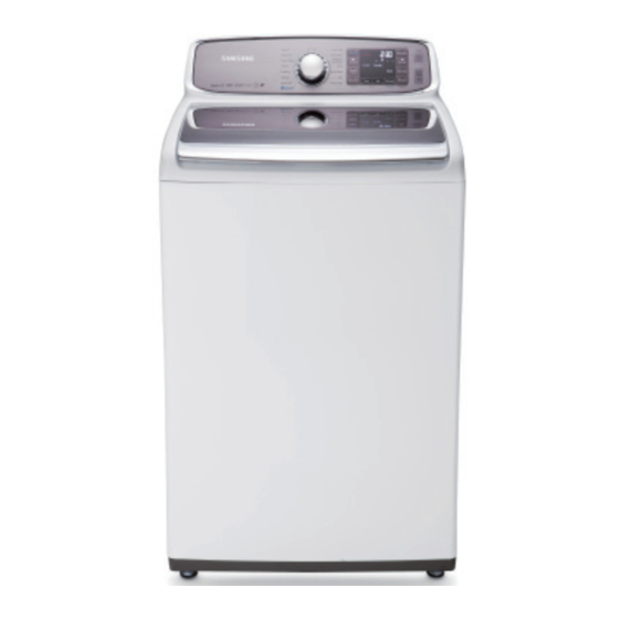
- Page 1 WASHING MACHINE TOP-LOADING TYPE Basic Name : WA422PRHD* (WA-HUDSON PJT) Basic Code : WA422PRHDWR/AA Model Name : WA45H7000AW (WA-7000HA PJT) Model Code : WA45H7000AW/A2 SERVICE Manual WASHING MACHINE (TOP-LOADING) CONTENTS 1. Safety Instructions 2. Features and Specifications 3. Disassembly and Reassembly 4. Troubleshooting 5.
-
Page 2: Table Of Contents
CONTeNTS 1. Safety instructions ..............1 1-1. -
Page 3: Safety Instructions
1. Safety InStructIonS 1-1. Safety InStructIonS for ServIce engIneerS ► Be sure to observe the following instructions to operate the product correctly and safely to prevent possible accidents and hazards while servicing. ► Two types of safety symbols, Warning and Caution, are used in the safety instructions. Hazards or unsafe practices that may result in severe personal injury or death. WarnIng Hazards or unsafe practices that may result in minor personal injury or property damage. cautIon WarnIng Before ServIcIng... - Page 4 WarnIng WHILe ServIcIng • Check if the power plug and outlet are damaged, flattened, cut or otherwise degraded. 4 If faulty, replace it immediately. Failing to do so may result in electric shock or fire. • Completely remove any dust or foreign material from the housing, wiring and connection parts. 4 This will prevent a risk of fire due to tracking and electrical hazard.. • When connecting wires, make sure to connect them using the relevant connectors and check that they are completely properly. 4 If tape is used instead of the connectors, it may cause fire due to tracking. • Make sure to discharge the PBA power terminals before starting the service. 4 Failing to do so may result in a high voltage electric shock. • When replacing the heater, make sure to fasten the nut after ensuring that it is inserted into the bracket-heater. 4 If not inserted into the bracket-heater, it touches the drum and causes noise and electric leakage. WarnIng after ServIcIng • Check the wiring. 4 Ensure that no wire touches a rotating part or a sharpened part of the electrical harness. • Check for any water leakage. 4 Perform a test run for the washing machine using the standard course and check whether there is any water leakage through the floor section or the pipes. • Do not allow consumers to repair or service any part of the washing machine themselves. 4 This may result in personal injury and shorten the product lifetime.
- Page 5 cautIon Before ServIcIng • Do not sprinkle water onto the washing machine directly when cleaning it. 4 This may result in electric shock or fire, and may shorten the product lifetime. • Do not place any containers with water on the washing machine. 4 If the water is spilled, it may result in electric shock or fire. This will also shorten the product lifetime. • Do not install the washing machine in a location exposed to snow or rain. 4 This may result in electric shock or fire, and shorten the product lifetime. • Do not press a control button using a sharp tool or object. 4 This may result in electric shock or damage to the product. cautIon WHILe ServIcIng • When wiring a harness, make sure to seal it completely so no liquid can enter. 4 Make sure that they do not break when force is exerted. • Check if there is any residue that shows that liquid entered the electric parts or harnesses. 4 If any liquid has entered into a part, replace it or completely remove any remaining moisture from it. • If you need to place the washing machine on its back for servicing purposes, place a support(s) on the floor and lay it down carefully so its side is on the floor. 4 Do not lay it down on its front. This may result in the inside tub damaging parts. Safety Instructions _ 3...
- Page 6 cautIon after ServIcIng • Check the assembled status of the parts. 4 Now is a good time to inspect your work. Review all connections and wiring, including mounting hardware. • Check the insulation resistance. 4 Disconnect the power cord from the power outlet and measure the insulation resistance between the power plug and the grounding wire of the washing machine. The value must be greater than 10MΩ when measured with a 500V DC Megger • Check whether the washing machine is level the floor with respect to the original position of the washing machine prior to service. By doing this now will reduce for the need of customer dissatisfaction and redo call. 4 Vibrations can shorten the lifetime of the product. 4 _ Safety Instructions...
-
Page 7: Features And Specifications
2. Features and speciFications 2-1. Features Features Description • Even bulky garments and blankets get super clean. The Great capacity The Great Capacity leaves enough room for a more thorough, cleaner wash. • The power to handle anything! Our direct-drive inverter motor delivers power right to the washer tub from a variable speed, reversible motor. Beltless DD Motor direct-drive motor generates a higher spin speed for more effective, quiet operation. The washer also has fewer moving parts, meaning fewer repairs. • A separate nozzle has been adopted that sprays water equally so that the Mist Shower rinse cycle is effective even with a small amount of water. • This Samsung washer performs smoothly at top spin speeds, minimizing ® (Vibration Reduction Technology) noise and vibration. • Clean your drum with one button! This Pure Cycle is specially designed to Self Clean remove detergent residue & dirt bulid up in the tub, without the need for (Tub Cleaning cycle) special chemical detergents. EZ-Closed Lid • The door is designed to close softly and prevent users from being injured Features and Specifications _ 5... -
Page 8: Specifications
2-2. speciFications tYpe top LoadinG WasHer A. Height 43.9″ / 111.5cm B. Width 27.0″ / 68.6cm DIMENSION (Inches / cm) C. Height with Door open 58.1″ / 147.6cm D. Depth 29.3″ / 74.4cm WATER PRESSURE 20~116psi (137~800kPa) WEIGHT 57kg (125.7 lb) CAPACITY 4.5cu.ft WASHING 120V 700W POWER SPIN 120V 400W CONSUMPTION DRAIN 120V 80W SPIN REVOLUTION 800rpm 6 _ Features and Specifications... -
Page 9: Detail Features
2-3. detaiL Features Grade WA45H7000A* WA422PRHD* image Capacity(DOE) 4.5 4.2 Aqua Jet Smart Care Diamond interior drum Yes Yes Self Clean Yes Yes Washing Cycles Main spec. Internal Heater Yes Yes ® Pulsator material Max rpm 800 800 (Max spin speed) Mist Shower Motor Color Neat White Neat White Main display Jog Dial Chrome Chrome LED color Ice-blue Red design... -
Page 10: Options Specifications
2-4. options speciFications item item name Code No. remark HOSE-HANGER DC61-00224A Default MANUAL-BOOK DC68-03133P Default CABLE TIE 6501-000121 Default CAP W.V DC61-10449Q Default ASSY-LEG SUPPORT DC97-14095A Service Note • Customer can purchase Water supply, drain hoses and assy leg support from a service center. 8 _ Features and Specifications... -
Page 11: Disassembly And Reassembly
3. Disassembly anD Reassembly 3-1. Tools foR Disassembly anD Reassembly Tool Type Remarks 10mm Tub(16), Fixer screw(5), Motor(1), Balance(5) Box driver 17mm Damper(2), Damper(friction 1) 10mm Replaced by box driver Double-ended spanner 17mm A Tool for protecting empty turning of bolt or abrasion from using box driver Vice pliers For disassembly of Spin drum... -
Page 12: Standard Disassembly Drawings
3-2. sTanDaRD Disassembly DRawings ► This is a standard disassembly diagram and may differ from the actual product. Use this material as a reference when disassembling and reassembling the product. Part figure Description 1. Remove the 6 screws holding the control panel assembly. 2. Separate the both hooks. (Left and Right) 3. Separate the cover panel upward. If it is difficult to disassemble, use the (-) driver to disassemble hooks. (Be careful damage of hooks.) sub and main PCb assembly 4. Remove the 2 screws holding the control panel assembly and turn the panel over. 5. Pull the Encoder-Knob to separate it and then remove the 4 fixing screws. When reassembling the PCB, take care that you do not damage the control-panel fixing hook. After replacing the sub PCB, check the key operation. - Page 13 Part figure Description 1. After separating the control panel, separate the water-valve housing. 2. Remove the 3 fixing screws. water Valve 3. Remove the wire-harness and release the 2 clamps connecting the hoses. When releasing the clamps, take care that you do not tear the hoses. Disassembly and Reassembly _ 11...
- Page 14 Part figure Description 1. Remove the 2 inlay tapes. Door assembly 2. Remove the 4 screws holding the door lid TC and separate the door. 12 _ Disassembly and Reassembly...
- Page 15 Part figure Description 1. Remove the 2 screws from the cover plate. 2. Separate the control panel assembly. 3. Separate the Assy Valve Water, the main PBA, the Assy Sensor Pressure and the filter EMI housing. Separate the housing to prevent stress and damage to the wire- Top Cover assembly harness. / Door switch 4. Separate the main wire harness, the pressure switch hose clip , Grounding screw .
- Page 16 Part figure Description 1. Separate the back cover 2. Separate 2 clamps. 3. Remove the 13 screws in base. Drain-Pump 4. Remove the 3 screws 5 screws are separated by ‘+’ shape hand driver. Thermistor 1. Remove the 2 screws. 14 _ Disassembly and Reassembly...
- Page 17 Part figure Description 1. Separate the top cover assembly by lifting and pushing ahead the top part of the assembly 2. Remove the 2 screws holding the panel control Separate all the wires connected to the housing. 3. Remove the 4 screws fixing the tub- cover and separate the tub-cover. Clutch assembly (continued) 4. Separate the pulsator-cap by inserting the tip of a (-) screwdriver between the pulsator-cap and the pulsator and then lifting the screwdriver up (↑).
- Page 18 Part figure Description 6. Remove the shaft with the jig wrench. - Release the nut in a clockwise direction. - Fasten the nut in a counterclockwise direction. 7. Place the main body so that the front frame faces upward and remove the 4 bolts holding the saddle with a 10mm wrench. When you place the washer on the floor, take care that you do not damage or scratch the product. Clutch assembly (continued) 8. Remove the bolt holding the DD-motor housing with a 17mm wrench and then remove the motor housing.
- Page 19 Part figure Description 10. Separate the 2 marked housings and then remove the DD-motor. 11. Press the hook to separate the housing. Clutch assembly (continued) 12. Separate the slide guide and the coupling by pulling them forward. Disassemble the coupling and the spring. Disassembly and Reassembly _ 17...
- Page 20 Part figure Description 13. Separate the clip. Clutch assembly (continued) 14. Remove the all screws fixing the clutch assembly and then separate the clutch assembly. Reassembly procedures are in the reverse order of dissasembly procedures. 18 _ Disassembly and Reassembly...
-
Page 21: Troubleshooting
4. TroubleshooTing 4-1. error modes ► This is a washer integrated error mode. For detailed information, refer to the general repair scripts. error Type For usA Causes remarks - The part of the hose where the water level sensor is located is damaged (punctured). - The hose is clogged with foreign material. - The hose is folded. - Too much lubricant has been applied to the insertion part of the Water level air hose. sensor - Hose engagement error. (disengaged) - Part fault. (Faulty internal soldering) - Page 22 error Type For usA Causes remarks - Check the consumer’s power conditions. : Make sure to check the operating voltage. Connect a tester to the internal power terminals during the Boil or Dry operations and observe the washing machine’s operation carefully. Power error 9E1,9E2 : Check the voltages. (An error occurs when under or over voltage is supplied.) : Check whether a plug receptacle is used. When the connecting wire is 1m, a momentary low voltage may drop up to 10 V - Main PBA fault (sometimes) - The signals between the sub and main PBAs are not sensed because of commuication error. - Check the connector connections between the sub and main PBAs carefully. → Check for incorrect or loose connections, etc. - Remove the sub PBA C/Panel and check for any faulty soldering. - The signals between The DR Module and main PBAs are not sensed because of commuication error. - Check The connector connections between The DR Module and main PBAs carefully.
- Page 23 error Type For usA Causes remarks - A switch contact error because of a deformation of the door When the door is not hook. opened after the door open operation. - When the door is pulled by force. When the door is not - This occurs in the Boil wash because the door is pushed due locked after the door to a pressure difference from internal temperature changes. door error close operation. - The door lock switch terminal is connected incorrectly. - The door lock switch terminal is broken. - This occurs intermittently because of an electric wire leakage - Main PCB fault. - The washing heater is short-circuited or has a wire disconnected. - The washing heater in the tub has an error. If the heater has no (Contact error, temperature sensor fault) error, this occurs heater error HE,HE1 - If the water level sensor operates without water because water because of a PBA relay...
- Page 24 error Type For usA Causes remarks - Error detected in the Mems PBA or data error detected. Check the wire connections. Replace if necessary. mems PbA error 1. Check the wire connections. detected 2. Replace the Mems PBA. 3. Main PBA wire connection error or PBA’s silver nano part malfunction. Replace if necessary. system error - Micro Controller Operation Fail. Replace Assy PCB. 22 _ Troubleshooting...
-
Page 25: Corrective Actions For Each Error Code
4-2. CorreCTive ACTions For eACh error Code Troubleshooting _ 23... - Page 26 24 _ Troubleshooting...
- Page 27 Troubleshooting _ 25...
- Page 28 26 _ Troubleshooting...
-
Page 29: The Installation For Leveling
4-3. The insTAllATion For leveling Problem Type Causes Corrective Actions If the rear level of the floor is lower than • Only use the front legs to adjust the • Use the leg supports to adjust the level the front level of the floor, it can’t be level. of the rear. leveled. • If the floor is on a steeply slope, please use the additional leg supports. Front Rear • Customer can purchase the leg supports from a service center. Troubleshooting _ 27... -
Page 30: Pcb Diagram
5. PCB Diagram 5-1. main PCB ► This Document can not be used without Samsung’s authorization. Location Part no. Function Description Location Part no. Function Description Motor Control Control to Motor Switching IC Making a stable DC Main Relay Main Power Relay Trans Circuit Chopping the DC Link SSR1~6 FUSE Limit the Over-Current Load Control Turn ON/Off the Load(Valve etc.) TRIAC1~2 Making DC Voltage It works to Change the AC to the DC Door Lock Switch • Drive the Door Lock Switch Q5,RY2 Driving Circuit • Toggle CW/CCW Charging Voltage... -
Page 31: Detailed Manual For Connector And Relay Terminal Part - Main Pcb
5-2. DetaiLeD manuaL For ConneCtor anD reLay terminaL Part - main PCB ► This Document can not be used without Samsung’s authorization. ► Cn4 ► Cn5 1. Bleach Valve (WA456*) 1. Water Level 2. Rinse Valve 2. Standby 3. Hot Valve 3. TX 4. Cold Valve 4. RX 5. Pump 5. Sub Reset 6. N.C 6. 5V... -
Page 32: Sub Pcb
5-3. SuB PCB ► This Document can not be used without Samsung’s authorization. Location Part no. Function Description Micom201 Control Function Control Key and LED Function SW601 Jog Dial Jog Dial CN802 Wash Communication Part Connect wash Main PBA CN501 Conecting Sensing Part Connecting Thermistor, cluch, Water Lavel LED Lamp Display Function BZ601 Buzzer Making a sound SW701~SW708,SW201 Switch Operating or changing Function DSP702 LED Display Display Funciton 30 _ PCB Diagram... -
Page 33: Detailed Manual For Connector Terminal Part - Sub Pcb
5-4. DetaiLeD manuaL For ConneCtor terminaL Part - SuB PCB ► This Document can not be used without Samsung’s authorization. ► Cn501 1. NC 2. NC ► Cn802 3. NC 1. CLUTH 4. NC 2. WL_MAIN 5. NC 3. STANDBY 6. NC 4. TX 7. GND 5. RX 8. WATER_THERM 6. RESET 9. CLUTCH_SEN 7. 5V 10. WATER_SEN1 8. GND... -
Page 34: Wiring Diagram
6. Wiring Diagram 6-1. Wiring Diagram ► This Document can not be used without Samsung’s authorization. nreference information BLACK BLUE GREEN GRAY NATURAL ORANGE PINK SKYBLU SKYBLUE VIOLET WHITE YELLOW 32 _ Wiring Diagram... -
Page 35: Reference
7. RefeRence 7-1. Model nuMbeR naMing Rules Reference _ 33... - Page 36 This Service Manual is a property of Samsung Electronics Co.,Ltd. © 2013 Samsung Electronics Co.,Ltd. All Any unauthorized use of Manual can be punished under applicable rights reserved. International and/or domestic law. 29 DEC. 2013...
Need help?
Do you have a question about the WA422PRHD Series and is the answer not in the manual?
Questions and answers
Water not draining from washing machine
Water may not be draining from the Samsung WA422PRHD Series washing machine due to the following reasons:
- The drain hose is clogged, especially at a narrow section.
- Sand or debris from items like throw rugs or doormats has accumulated inside the washer.
- The drain pump filter cover is engaged incorrectly.
- Water leakage is occurring at the drain hose.
- The water level sensor is degraded or its terminal is out of place.
- There is an injection error caused by a clogged drain hose.
- The duct condensing holding screws are worn or incorrectly fastened.
These issues can prevent proper drainage and may trigger error codes like "OE" (Overflow Error).
This answer is automatically generated