Advertisement
Quick Links
Advertisement

Related Manuals for Control Concepts SMAUFUSION-RDK5

Summary of Contents for Control Concepts SMAUFUSION-RDK5
- Page 2 CONTROL CONCEPTS, INC. warrants that the products delivered will be as described in the sales order or contract. CONTROL CONCEPTS, INC. warrants to the original user that CONTROL CONCEPTS, INC. products will be free from defects in materials and workmanship for a period of two (2) years after the date CONTROL CONCEPTS, INC. ships such products.
- Page 4 The Remote Display can connecT to any MicroFUSION or FUSION controller to view and change parameters on the Screen List. The Remote Display will display the Default Screen List when first connected to a controller. This list is quite extensive and can be cumbersome, therefore it is recommended to create a Custom Screen List using the Control Panel Software for a more practical experience. ...
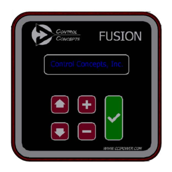
- Page 5 DISPLAY SCREEN A 2-Line Display that shows information about a selected parameter. MOVEMENT The Up/Down Movement arrows are used to navigate between parameters. In addition, when a parameter is selected the Movement arrows move the 2-Line Display cursor left or right to assist in setting the parameter value. SELECT The green Select button is used to enter and exit parameters.
-
Page 6: Mounting Considerations
The Remote Display kit includes all necessary components (excluding knockout punch) to mount the Remote Display to the front of an electrical enclosure. This allows for easy viewing and adjustment of parameters and reduces costs by eliminating the need for external gauges. The Remote Display meets CE and UL requirements. -
Page 7: Installation Complete
5. Remove the (1 Ft) cable from the Remote Display. Run one end of the (5/25 Ft) Ethernet cable to the Remote Display connector on the side of the controller (Figure 3.04). 6. Attach the other end of the Ethernet cable to the connector on the Remote Display. Place the ferrite as close to the connector as possible (Figure 3.05). - Page 8 5. Attach the Rear Housing with provided mounting screws. When tightening down the Remote Display make sure to apply equal pressure to each screw to ensure the gasket seals properly. When properly installed the gasket shall be compressed 50% on all sides. If the gasket becomes damaged during installation please contact Control Concepts, Inc. for a replacement.
- Page 9 Review Chapter 2: Points of Interest for clarification of button keywords. The Remote Display is manipulated using a five button interface which allows a user to view/change parameters of a connected controller. The parameters shown on the 2-Line Display are called from a ‘Screen List’, Figure 4.00 shows examples of how those ‘screens’...
- Page 10 A parameter lock can be setup to prevent anyone from changing parameter values using the Remote Display keypad. Refer to the Control Panel User’s Manual for details on locking parameters on the Remote Display. The Remote Display has two categories of screens: Remote Node Monitor and Client Display Configuration. When first powered-on, the Remote Display will cycle through the first 8 screens of the default or user-set Screen List.
- Page 11 [MP 26] Network Status Units: Binary Format: xxxxxxxx Representation: Buss-Off: The Remote Display is Off-Line / In Error Bus - Passive: The Remote Display has detected network errors, but is not Off-Line DUP MAC: The Remote Display is Off-Line due to another node having the same MAC ID Timeout: The connection with the server node timed out Not Used...
-
Page 12: Step 1: Screen List
Setup for the Remote Display can be completed in three easy steps. Step 1: Screen List - Connect the controller to Control Panel and verify that the MAC ID is unique on the network. If the controller has not yet been setup, refer to the appropriate User’s Manual. - Page 13 Are the Remote Display cables in the same wiring path as other voltage carrying wires? No. The Remote Display is powered and has interaction with the connect controller only through the shielded Ethernet cables. Why doesn’t the Remote Display turn on? 1.
- Page 14 Remote Display Kit Cable Length MicroFUSION FUSION 5 Ft SMAUFUSION - RDK5 SMAFUSION - RD5 15 Ft SMAUFUSION - RDK15 SMAFUSION - RD15 25 Ft SMAUFUSION - RDK25 SMAFUSION - RD25 Ethernet Cables Length MicroFUSION FUSION 5 Ft 0058007 - 0050 - 05 0058003 - 0050 - 05 15 Ft 0058007 - 0050 - 15 0058003 - 0050 - 15 25 Ft...
Need help?
Do you have a question about the SMAUFUSION-RDK5 and is the answer not in the manual?
Questions and answers