Xtool D1 Pro 40 W Manual
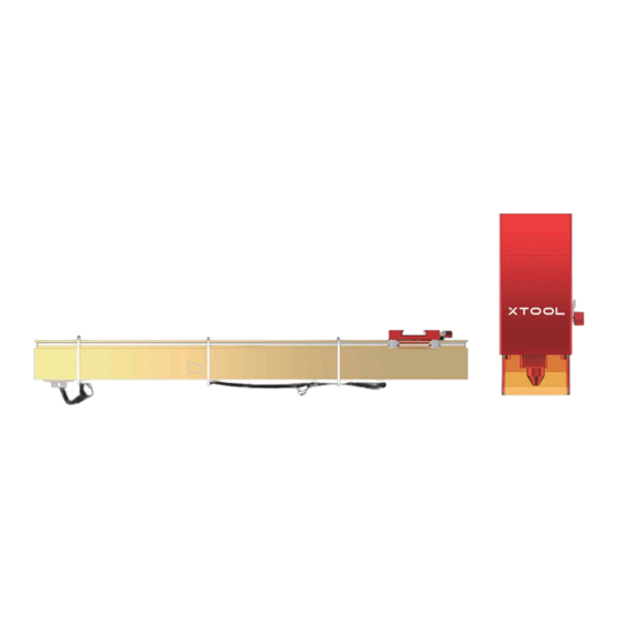
Laser module kit
Hide thumbs
Also See for D1 Pro 40 W:
- Quick start manual (27 pages) ,
- Manual (6 pages) ,
- Quick start manual (8 pages)

Related Manuals for Xtool D1 Pro 40 W


Summary of Contents for Xtool D1 Pro 40 W
- Page 1 D1 Pro 40 W xTool D1 Pro 40 W Laser Module Kit Laser Module Kit KD010553000 KD010553000...
-
Page 2: Table Of Contents
Use the focal length setting piece for the infrared laser module Clean the laser module xTool D1 Pro 40 W laser module kit provides two color options. This user manual Instructions uses the golden red version to describe how to modify and set up your machine. -
Page 3: List Of Items
List of items Power adapter Cable tie pack Parts storage box Main control board Laser module Position limit control board Screwdriver Cylindrical head Focal length screw M3*6 setting piece Position limit piece A Position limit piece B Middle plate Screw M4*16 Screw M4*25 Hex key... -
Page 4: Modify Your Xtool D1 Pro
Modify your xTool D1 Pro With this xTool D1 Pro 40 W laser module kit, you can modify your xTool D1 Pro into a 40 W one. 1. Remove the original middle plate Flat head Cylindrical head Round head screw M3*8... - Page 8 2. Replace the position limit control board If the position limit control board cannot be removed due to screw slipping, use the sharp-nose pliers to remove it. Exercise caution when doing this, protecting yourself from hurt.
- Page 9 3. Replace the position limit pieces...
- Page 10 4. Replace the main control board The largest processing area varies according to laser module. You need to set the (1) Remove the original main control board position of position limit piece A, accordingly. For laser module 40 W For laser module 20 W For laser module 10 W &...
- Page 12 (2) Install the new main control board 21 ...
- Page 13 5. Install the shaft and coupling back to the machine If you can't put the shaft through the timing belt, the possible cause is that the timing belt is set too tight. You can adjust its tension by turning the screw.
- Page 14 Keep a small distance between the coupling and motor, or the coupling can't rotate properly. Slide the two sliders down against the front plate. Do not tighten the screws here.
- Page 15 6. Install the new middle plate Fully tighten the two screws. Cut off the white cable ties, and keep the black ones.
- Page 17 The screw is used to set the tension of the timing belt. Do not fully tighten it. Otherwise, the timing belt may be damaged.
- Page 18 There are three holes designed for cable ties on the right plate. Do not attach a cable tie in the middle hole. It may interfere with the moving of the laser module.
- Page 19 7. Install the new laser module...
-
Page 20: Set Up The Machine
Set up the machine 1. Adjust the tension of the timing belt on the right plate Try to set the tension of the timing belt on the right plate to be the same as that Modification completed! of the timing belt on the left plate to ensure better engraving and cutting results. - Page 21 2. Set the position of the laser module...
- Page 22 3. Set the position of the rear plate on the laser module To cut thicker materials, you can adjust the position of the rear plate of the laser module to ensure better cutting results. After adjusting the position of the rear plate, you can still use the focal length setting bar to set the position of the laser module.
-
Page 23: Use The Focal Length Setting Piece For
Use the focal length setting piece for the infrared laser module If you use the infrared laser module on the machine, use the focal length setting piece delievered with the machine to set the position of the infrared laser module. -
Page 24: Clean The Laser Module
Clean the laser module For the 40 W laser module, you are advised to clean it, including the inner and outer frames of the light shield, lens, and red light outlet, every time after it has been used for one consecutive hour. 1. - Page 25 3. Clean the inner and outer frames of the light shield with tissues or dust-free cloth 2. Take the lens out of the laser module. moistened with alcohol; and clean the laser lens, nozzle, and red light outlet with a cotton swab moistened with alcohol.
- Page 26 4. Put the lens back to the laser module. 5. If you find the lens difficult to clean, you can replace it with a new one.
- Page 27 Vielen Dank, dass Sie sich für xTool-Produkte entschieden haben! La société a rassemblé le contenu du manuel avec rigueur et attention, mais il est possible qu'il subsiste des erreurs ou des omissions.
- Page 28 Benvenuti all’utilizzo dei prodotti xTool! Muito obrigado por escolher a xTool! Se utilizzi il prodotto per la prima volta, leggi attentamente tutti i documenti forniti per un’esperienza migliore. Se non si utilizza il prodotto secondo le istruzioni e i requisiti del Se estiver a usar o produto pela primeira vez, leia atentamente todos os materiais que acompanham o produto para melhorar a sua experiência com ele.
- Page 29 제품을 구입해 주셔서 감사합니다 ! 欢迎使用 xTool 产品! 본 제품을 처음 사용하는 경우 제품과 함께 제공되는 모든 자료를 주의 깊게 읽으시면 더 나은 사용 경험을 즐기실 수 있습니다. 본 사용설명서의 지시 및 요구사항에 따라 본 제품을 사용하지 않거나, 이해 부족 등으로 제품을...
- Page 30 FCC statement Declaration of conformity | Konformitätserklärung | Declaración de conformidad | Déclaration de con- formité | Dichiarazione di conformità | CONFORMITEITSVERKLARING | Declaração de conformidade Frequentes This device complies with Part 15 of the FCC Rules. Operation is subject to the following two conditions: (1) This device may not cause harmful interference, and (2) This device must accept any interference received, including interfer- ence that may cause undesired operation.
- Page 31 更多售後資訊 , 請前往 。 Weitere Informationen über Kundendienstleistungen finden Sie unter support.xtool.com. support.xtool.com 线材 Para soporte técnico, contáctese con nosotros a través de support@xtool.com. 更多产品信息, 可访问 Para más información acerca de los servicios posventa, visite support.xtool.com. makeblock.com/cn/docs 如需技术支持, 可通过以下方式联系我们: • QQ 技术支持:...
- Page 32 FAQs | Häufig gestellte Fragen | Preguntas frecuentes | FAQs | Domande frequenti (FAQ) | FAQs | Perguntas Frequentes | よくある質問 | 자주�묻는�질문 | 常見問題集 | 常见问题 Cuando ajusto la velocidad de procesamiento del mapa de bits Lorsque je définis la valeur de traitement bitmap sur une a un valor grande, el módulo láser tiembla cuando está...
- Page 33 「ビットマップを加工する際、 処理速度を大きい値に設定すると、 レーザーヘッ Durante il funzionamento, se imposto la velocità di elaborazi- Wanneer ik de verwerkingssnelheid van de bitmap op een Quando ajusto a velocidade de processamento do bitmap para ドが振動し、 彫刻効果が低下します。 その理由と対処法は?」 one bitmap su un valore elevato, il modulo laser trema, hoge waarde instel, maakt de lasermodule tijdens het werken um valor grande, o módulo de laser tremula em funcionamen- causando scarsi risultati di incisione.
- Page 34 · 適當減緩加工速度 , 以達到更完美的雕刻效果 。 • 기계는�반드시�땅바닥�등�평평한�곳에서�사용하여�소재�가공�시�떨림이 발생하지�않도록�합니다. 加工位图时, 一旦使用高速加工, 激光头会发生抖动, 导致雕刻效果变差, 为什么, • 라이저는�사용을�금합니다. 라이저를�사용하면�기계의�무게�중심이�높아져 怎么处理? 안정성이�떨어지게�됩니다. 由于每个用户使用的电脑性能有差异, xTool D1 Pro采用的是电脑一边生成数据, 一边传输给xTool D1 Pro 加工的方法, 所以在使用性能较低的电脑时, 就会出现 • 각인�품질이�나빠질�우려가�있으므로�가공�속도를�줄여�주십시오. 在线加工卡顿、 抖动的现象。 推荐方式如下: 使用高性能的电脑或离线加工: 确保电脑的传输Gcode文件的效率不拖后腿。 • 在不会晃动的平台上加工 (例如地面) : 确保机架稳固。 •...
Need help?
Do you have a question about the D1 Pro 40 W and is the answer not in the manual?
Questions and answers