
Related Manuals for Summit FMX60

Summary of Contents for Summit FMX60
- Page 1 3379 Peachtree Road NE Suite 555 Atlanta, GA 30326 FMX60 FREE FLOATING REAR DISCHARGE FLEX HITCH FINISHING MOWER...
- Page 3 TO THE PURCHASER This manual contains valuable information about your new Summit Tractor Flex Hitch Rear Discharge Finishing Mower. It has been carefully prepared to give you helpful sug- gestions for operating, adjusting, servicing and ordering re- pair parts. Keep this manual in a convenient place for quick and easy reference.
- Page 4 Return the equipment or parts to the authorized Sum- mit Tractor dealer, from where it was purchased, for service or replacement of defective parts that are covered by warranty. (The Summit Tractor Factory may inspect equipment or parts before warranty claims are honored.)
-
Page 5: Table Of Contents
CONTENTS ITEM PAGE Safety ................. 6 Assembly Instructions ..........8 Before Putting Into Service ........10 Safety Training ............11 Transportation Safety ..........15 Attaching To Tractor ..........16 Sizing PTO ............... 18 Operating Instructions ..........19 Maintenance ............21 5 FT. -
Page 6: Safety
It may also be used to alert against unsafe prac- tice. If you have any questions not answered in this manual or require additional copies or the manual is damaged, please contact your dealer or Summit Tractor LLC 3379 Peachtree Road NE Suite 555 Atlanta, GA 30326 (678) 916-6555. - Page 7 EQUIPMENT SAFETY GUIDELINES Safety of the operator and by standards is one of the main concerns in designing and developing a mower. However, every year accidents occur which could have been avoided by a few seconds of thought and a more careful approach to han- dling equipment.
-
Page 8: Assembly Instructions
FINISHING MOWER ASSEMBLY INSTRUCTIONS STEP 1 With finishing mower still in crate, lay flat on a level surface. Remove the top & side sections of the crate, leaving the finishing mower resting on the bottom section. Set aside PTO shaft. STEP 2 Insert tail wheel arms as shown in Figure E and tighten both the bolt &... - Page 9 Figure D Figure C Figure E Figure F...
-
Page 10: Before Putting Into Service
BEFORE PUTTING FINISHING MOWER INTO SERVICE (IMPORTANT-INSTRUCTIONS PRIOR TO START UP) SHIPPED WITH OIL IN GEARBOX SHIPPED WITHOUT GREASE IN GREASE FITTINGS. UNIT MUST BE SERVICED BEFORE USING. When Adding Oil Use Multi-Purpose Gear Oil (I.E. S.A.E. 80w/90 or • S.A.E. -
Page 11: Safety Training
SAFETY TRAINING Safety is a primary concern in the design and manufacture of our product. Unfortu- nately, our efforts to provide safe equipment can be wiped out by a single careless act of an operator or bystander. In addition to the design and configuration of equipment, hazard control and accident prevention are dependent upon the awareness, concern, prudence and proper train- ing of personnel involved in the operation, transport, maintenance and storage of this equipment. - Page 12 PREPARTION Never operate the tractor and mower until you have read and completely un- derstand this manual, the Tractor Operator’s Manual, and each of the safety messages found on the safety signs on the tractor and mower. Personal protection equipment including hardhat, safety glasses, safety shoes, and gloves are recommended during assembly, installation, operation, adjustment, maintenance, repairing, removal, or moving the implement.
- Page 13 OPERATIONAL SAFETY The use of this equipment is subject to certain hazards that cannot be protected against by the mechanical means or product design. All operators of this equipment must read and understand this entire manual, paying particular attention to safety and operating instructions, prior to using.
- Page 14 OPERATIONAL SAFETY continued... Never allow the cutting blade to contact such items. Cut material higher at first, allow- ing finishing mower to clear hidden objects. Never assume an area is clear. Always Check! Always stop the tractor, disengage PTO, set brake, shut off the tractor engine, re- move the ignition key, lower implement to the ground and allow cutter blades to come to a complete stop before dismounting tractor.
-
Page 15: Transportation Safety
OPERATIONAL SAFETY continued... Pass finishing mower diagonally through sharp dips and avoid sharp drops to pre- vent “hanging up” tractor and finishing mower. Practice will improve your skills in maneuvering on rough terrain. Always cut down slopes, never across the face. Al- ways check tractor manual for proper use on slopes. -
Page 16: Attaching To Tractor
ATTACHING TO TRACTOR WARNING Never stand between tractor and finishing mower while backing up tractor to the hitch. STEP 1 Attach to tractor's category 1 three point hitch as described in the Tractor's Operator’s Manual. WARNING Failure to install retaining clip on gearbox input shaft would allow driveline to swing freely if bolt is sheared causing possible injury or death. - Page 17 6 inches of overlap. If PTO shaft has been marked for cutting the overlap is the distance measured between the two marks. If the PTO shaft has less than a 6 inch overlap, DO NOT USE. Contact your authorized Summit Tractor Dealer.
-
Page 18: Sizing Pto
SIZING PTO SHAFT STEP 1 Cutting the PTO shaft to length. NOTE: Be sure to cut equal lengths of each PTO shaft section. Clamp end of PTO shaft in a vice and cut off shield where marked. (Figure 1-A & 1-B) STEP 2 Using cut section of the shield as a guide Figure 1-A... -
Page 19: Operating Instructions
OPERATING INSTRUCTIONS This mower was designed to CUT LAWN GRASS ONLY. Use of your finishing mow- er to cut any material other than lawn grass may damage the mower and void your war- ranty. CUTTING HEIGHT ADJUSTMENT To prevent blades from striking the ground your finishing mower should be set to the highest position that will give desired grass height. - Page 20 FINISHING MOWER OPERATION STEP 1 Before each use perform the maintenance described in maintenance section (pg.# 21) STEP2 Read, understand, and follow the information on safety training, preparation, starting and stopping safety, operational safety, transport safety warning sections of this man- ual (pages 11 thru 16) STEP 3 With tractor running, lower finishing mower to ground so that the swivel links are par-...
-
Page 21: Maintenance
MAINTENANCE Periodically check and maintain proper gear oil level. Every 8 hours, grease spindles (3), roller axle (1), wheel forks (4), wheel axles (4), PTO shaft universal joints (2), and PTO telescoping surface. NOTE: Use only a grade Type II tube grease. Before each use check to make sure all safety features are installed and work- ing properly. -
Page 22: Ft. Belt Replacement
5FT. FINISHING MOWER TO REPLACE BELT: STEP 1 Remove top cover. STEP 2 Release adjustment spring. STEP 3 Loosen nut on adjustment pulley to allow for movement. (See Figure “D”) STEP 4 Loosen nut on right side of “L” bracket. (See Figure “D”) STEP 5 Loosen belt by moving adjustment pulley in opposite direction you would to tighten belt. - Page 23 Figure D...
-
Page 24: Maintenance Safety
MAINTENANCE SAFETY Good maintenance is your responsibility. Poor maintenance is an invitation to trouble. Follow good shop practices. Keep service area clean and dry Be sure electrical outlets and tools are properly grounded Use adequate light for the job at hand. Make sure there is plenty ventilation. -
Page 25: Safety Decal's And Locations
SAFETY SIGN LOCATIONS The types of safety signs and locations on the equipment are shown in the illustration below. Good safety requires that you familiarize yourself with the various safety signs, the type of warning and the area, or particular function related to that area, that re- quires your SAFTY AWARENESS REMEMBER: If safety signs have been damaged, removed, become illegible or parts have been replaced without signs, new safety signs must be applied. -
Page 31: Notes
NOTES:... -
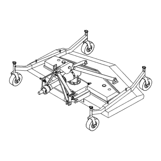
Page 32: Replacement Parts
FMX60 PARTS DIAGRAM... - Page 33 FMX60 PARTS Ref. No. Part Name FMX60 Top Cover 124685 Gear Box Plate 403025 Idler Pulley Bracket 312647 Spindle Unit - Single 502303 Idler Pulley - Single 164090 Belt Adjustment Assembly 403688 V– Belt* 167133 Spring 502027 Gearbox 184000 Main Pulley - Single 165114 Swivel Link Bolt Pkg.
-
Page 34: Hp Gearbox Parts
40 HP GEARBOX... - Page 35 Ref. Part Name 5’ Gearbox 184000 Snap Ring 106138 Input Seal (NAK 35 x 54 x 10) 156010 Front Cap 129015 Front Cap Gasket 124130 Snap Ring 131031 Snap Ring 131030 Bearing (Hoover 208) 155005 Input Gear 185007 Input Shaft 186010 Bearing (NSK 6207) 155010...
-
Page 36: Pto Shaft Parts
22" PTO 147022 Ref. Part Name 147022 Roll Pin Kit 500131 Male Tube End Yoke 151045 Implement End Yoke 151040 Female Tube End Yoke 151050 Tractor End Yoke 151035 Inner Tube 14 Series 151090 Outer Tube 14 Series 151091 Cross Kit # 4 170015 Quick Disconnect Pin 170110... -
Page 37: Spindle Unit Parts
Blade Spindle Unit Ref. No. Part Name 502303 Bearing Kit - (2) Ball Bearings (6205), 1 & 2 (2) Seals (TCM 25 x 52 x 7 TC), (4) Snap Rings 555009 Spindle Pulley /w Nut & Key 502313 Blade Bolt Set (3) /w Washer 502310 Spindle Cap 191302... -
Page 38: Pto Shaft Cover Removal
PTO SHAFTS COVER REMOVAL BONDIOLI- (BYPY) There are 3 white tabs around the cover as shown in (A in FIG. 1). Take a screwdriver and press against the tabs one at a time with downward angular pressure toward the end of shaft marked (B in FIG. 2). As you are pressing tab grasp cover at point marked (B in FIG. - Page 39 BONDIOLI COVER REMOVAL FIGURE- 1 FIGURE– 2 EUROCARDAN SERIES 4 COVER REMOVAL FIGURE– 3 FIGURE– 4 LA MAGDALENA COVER REMOVAL FIGURE– 5...
- Page 40 PTO SHAFTS COVER REMOVAL EUROCARDAN SERIES 5 There are 2 black tabs around the cover as shown in (B in FIG. 1). Take a flat screwdriver and pry under the tabs one at a time at point (B in FIG. 2) lifting tab over on top of (e-shaped lock).
- Page 41 PTO SHAFTS COVER REMOVAL PTO SHAFTS COVER REMOVAL Separate the two halves of the drive line. Locate the bearing clip at either end of the driveline. Insert a flathead screw driver into the groove indicated in (Figure 11), below. W hile pressing inward on the arm of the bearing clip, rotate the bearing clip in the counter clock wise direction in (Figure 12).
- Page 42 PTO SHAFTS COVER REMOVAL RPM Continued With the bearing clips disengaged, locate the bearing tabs at either ends of the drive line (Figure 13). Insert a flathead screwdriver in the groove indicated in (Figure 14), below. Rotate the bearing tab approximately an eighth of a turn in the counter clockwise direction.
- Page 43 PTO SHAFTS COVER REMOVAL RPM Continued With the bearing disengaged, remove the shield from each end of the driveline. Figure 15 (Step 4) Locate the bearings at either end of the driveline. Rotate each end of the driveline until the split in each bearing is visible. Figure 16 (Step 5)
- Page 44 PTO SHAFTS COVER REMOVAL RPM Continued Pull outward on the tabs adjacent to the split in the bearing to remove the bearings from either end of the driveline. Please refer to Figure 18, below, for a disassembled driveline. Figure 17 (Step 6) Figure 18 (Step 6)
-
Page 45: Warranty
All warranty service will be performed at service centers desig- nated by Summit Tractors. If Summit Tractors is unable to repair the product to conform to the warranty after a rea- sonable number of attempts, Summit Tractors will provide, at its option, one of the following: (a) a replacement for the product or, (b) a full refund of the purchase price.
Need help?
Do you have a question about the FMX60 and is the answer not in the manual?
Questions and answers