Advertisement
Quick Links
Advertisement
Troubleshooting

Related Manuals for Grozone Control TV2


Summary of Contents for Grozone Control TV2
- Page 1 USER GUIDE Temp-2V Fan Speed Control www.grozonecontrol.com...
-
Page 2: Table Of Contents
TABLE OF CONTENTS SAFETY NOTICE PRODUCT DETAILS 4-5-6 INSTALLATION SETTINGS QUICK TROUBLESHOOTING GUIDE 10-11 COMPLETE TROUBLESHOOTING GUIDE 12-13 WARRANTY & CUSTOMER SERVICE 14-15... -
Page 3: Safety Notice
SAFETY NOTICE IMPORTANT SAFETY INSTRUCTIONS SAVE THESE INSTRUCTIONS DANGER TO REDUCE THE RISK OF FIRE OR ELECTRIC SHOCK, CAREFULLY FOLLOW THESE INSTRUCTIONS. To reduce the risk of electric shock, disconnect power to the 120V electrical outlet before installing or removing the unit. When removing the electrical wall plate, it may fall across plug pins or become displaced. -
Page 4: Product Details
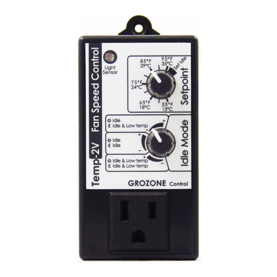
PRODUCT DETAILS Opera on and Specifica ons Temperature setpoint between 55°F and 95°F / 13°C to 35°C. 6- temperature probe works from +32°F to 212°F (0°C to 100°C). The 120V output is variable. Max 750 Wa s, 6.2 Amps. 2 seconds «KickStart» at startup. (100% power to improve or ensure fan startup). - Page 5 PRODUCT DETAILS...
- Page 6 PRODUCT DETAILS...
-
Page 7: Installation
INSTALLATION Note: Designed for single phase 120VAC induc on motor fans up to 750 Wa s. Light sensor (photocell) Plug into 120 VAC outlet (see security no ce on page 1). Place the sensor at desired loca on. Connect the fan into the front panel outlet (MAX 750W, 6.2A). Note: For mul ple fan applica on, use a power bar. -
Page 8: Settings
SETTINGS IDLE MODE & SPEED SETTINGS (Idle speed = minimum speed) Turn top knob fully clockwise into «Set Idle» zone. Upper Mode Turn knob between «-» and «+» signs in UPPER sec on to set Idle speed. Day: Fan runs between idle speed and full speed. Night: Operates same as day me but fan will stop if a low temperature condi on is met (*). - Page 9 SETTINGS Lower Mode Turn knob between «-» and «+» signs in LOWER sec on to set Idle speed. Day and Night: Fan runs between idle speed and full speed but will stop if a low temperature condi on is met (*). (*) The low temperature condi on is met when actual temperature is colder that (SETPOINT -10°F/-4,5°C).
-
Page 10: Quick Troubleshooting Guide
QUICK TROUBLESHOOTING GUIDE... - Page 11 QUICK TROUBLESHOOTING GUIDE...
-
Page 12: Complete Troubleshooting Guide
COMPLETE TROUBLESHOOTING GUIDE Mul mode Fan Speed Controller 1 – Before you start ***IMPORTANT: READ AND FOLLOW THESE INSTRUCTIONS BEFORE STARTING THE TEST. DO NOT CONNECT THE UNIT BEFORE STEP 1 OF THE TEST. · CONNECT A FAN IN THE FRONT UNIT OUTPUT. ·... - Page 13 COMPLETE TROUBLESHOOTING GUIDE STEP HANDLING AND TEST DESCRIPTION EXPECTED RESULTS Turn LOWER knob fully CW. The fan will return to · Turn UPPER knob slightly CCW to set 60% INTENSITY · the knob line between 90°F and 95°F. (dimmer effect). The fan will turn OFF Cover the Light Sensor completely ·...
-
Page 14: Warranty & Customer Service
WARRANTY & CUSTOMER SERVICE DO YOU HAVE A PROBLEM WITH YOUR CONTROLLER ? PLEASE READ THESE INSTRUCTIONS CAREFULLY AND SAVE THEM FOR FUTURE REFERENCE. 1. I think my controller is damaged, or it simply does not work as indicated in the user guide, what should I do? Please refer to the troubleshoo ng steps. - Page 15 To avoid being charged for the accessories, be sure to include all pieces. Thanks for your coopera on. Any Grozone Control product that is returned with obvious signs of user · neglect will not be covered by the warranty. Grozone Control exercises the right to make final decisions in these ma ers.
- Page 16 Rev. 3.0 www.grozonecontrol.com...
Need help?
Do you have a question about the TV2 and is the answer not in the manual?
Questions and answers