
Related Manuals for Unitor HPCE DYNAMIS 500+


Summary of Contents for Unitor HPCE DYNAMIS 500+
- Page 1 Unitor™ HPCE DYNAMIS 500+ OPERATIONS MANUAL Model: HPCE DYNAMIS 500+ WSS Part Number: 720131 Last Revision: October 2023 (Rev. 1.4) OPERATIONS MANUAL Rev. 1.4...
-
Page 2: Table Of Contents
Contents Technical Data HPCE Dynamis 500+ ......................3 Important Safety Precautions ........................4 Type plate and serial number ........................6 Introduction ..............................7 Water quality requirements ........................8 Details about lifting means .......................... 9 Machine Description ..........................10 Electrical Control Cabinet ........................16 Electrical Diagram ........................... -
Page 3: Technical Data Hpce Dynamis 500
Technical Data HPCE Dynamis 500+ Nominal voltage 380V/440V 3ph Nominal frequency 50Hz/60Hz Nominal power rating 16 KW – 32,6A @380V/50Hz 19,2 KW – 32,6 A @440V/60Hz Motor protection type CLASS F / IP 55 Recommended breaker 50 A, class D or K Pump type W5018 HR Pump oil type... -
Page 4: Important Safety Precautions
Important Safety Precautions Before using the machine ensure this operations manual is fully read and understood. Always keep this manual in a safe place near to the machine. Never let persons, who are not trained work with the machine This machine should be operated by qualified personnel only Τhe operator must always wear appropriate and certified personnel protective equipment (PPE) for 500 bar. - Page 5 Always check and ensure that the machine and its accessories (hoses, cables, fittings, spray handle, nozzle etc.) are in good working condition before start-up. The maximum permissible pressure and temperature are printed on the high- pressure hose. In case of damage, replace immediately with original approved hoses.
-
Page 6: Type Plate And Serial Number
Location of equipment • Your water jetting unit is designed to be placed and operated under normal environmental conditions according to DIN 500100-1 and DIN 50014. When you transport the high pressure cleaner on vehicles or trucks please fasten it on a suitable transport pallet. -
Page 7: Introduction
Introduction This manual or part of it should not be reproduced without the written approval of the manufacturer. Every effort has been made to ensure that the information in this manual is both accurate and current. However, we reserve the right to change, alter or otherwise improve the product and its documentation at any time without prior notice. -
Page 8: Water Quality Requirements
Water quality requirements The environment temperature when the high-pressure cleaner operates should be min +4°C and max + 40°C. Notes on the requirements for the water used. The STANDARD pumps work with clean, soft water, at a maximum temperature of 40˚C, and only for short periods, up to 60˚C. -
Page 9: Details About Lifting Means
Details about lifting means Instructions for lifting process The water tank must be empty. • Check water tank valve before lifting the machine. • • The high-pressure hose must be lifted separately. Lifting should only be done with certified lifting straps according to ΕΝ 1492-1 (Flat woven webbing sling). -
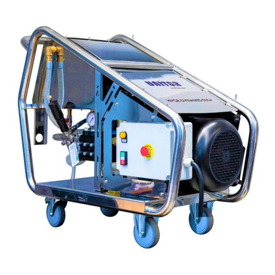
Page 10: Machine Description
3. Water tank inlet 4. Lifting eyes 5. High pressure gauge 6. Unloader – bypass valve 7. HP pump 8. Rear wheels with brake 9. Water tank 10. Unitor cover 11. Electric motor 12. Electrical cabinet 13. Front wheels OPERATIONS MANUAL Rev. 1.4... - Page 11 14. Handle 15. Water tank 16. Unitor cover 17. Inox frame 18. Electrical cabinet 19. Electric motor 20. Front wheels 21. HP lance and spray handle 22. Overfill drain 23. Overfill drain hose 24. Inlet water cartridge filter 25. HP pump 26.
- Page 12 27. Water tank inlet 28. Thermal valve 29. HP outlet fitting, 24mm 30. Unloader – bypass valve 31. LP hose from tank to pump 32. High pressure gauge 33. Safety valve with drain hose 34. High pressure connection set (x2) 35.
- Page 13 36. Water filter, inlet pressure gauge 37. Water tank mesh filter 38. Pump oil level indicator 39. Water filter, outlet pressure gauge 40. Water tank drain valve 41. HP hose bend protector OPERATIONS MANUAL Rev. 1.4...
- Page 14 42. Unloader hose 43. Pump oil filler 44. Pump oil drain 45. Handle 46. Water tank inspection cover 47. Overfill drain 48. Water inlet connection ¾’’ with GEKA coupling 49. Inlet water cartridge filter OPERATIONS MANUAL Rev. 1.4...
- Page 15 50. Thermal valve 51. Water tank overfill valve 52. Water tank drain 53. Water tank outlet 54. Bypass water diffuser 55. Low water level switch OPERATIONS MANUAL Rev. 1.4...
-
Page 16: Electrical Control Cabinet
Electrical Control Cabinet 1. Terminal ground 6mm 2. Fuse Terminal 3. Terminal 4mm 4. Mini relay with base 5. Timer 6. Hour meter 7. Breaker 3P 8. Relay 38A 9. Thermal relay 10. Transformer 440V / 24V OPERATIONS MANUAL Rev. 1.4... - Page 17 11. Low water level indication lamp 12. Start/Stop push button (with white indication lamp) 13. Emergency stop button OPERATIONS MANUAL Rev. 1.4...
-
Page 18: Electrical Diagram
Electrical Diagram OPERATIONS MANUAL Rev. 1.4... -
Page 19: Description And Function Of The Safety Installations
Description and Function of the Safety Installations Unloader Valve for Bypass Mode • The high-pressure valve limits the operating pressure. When the maximum operating pressure is exceeded or the handle is closed, the unloader valve administrates the water over a bypass connector back to the water tank through the water diffuser. -
Page 20: Operating The Machine
Operating the machine Check points before start-up • Place the high-pressure cleaner on a plain and secure it against rolling. • Check the oil level of the high-pressure pump. If it is too low, refill oil. (Pump oil specification: SAE 15W40 ISO VG100 DIN 51524) Maximum oil level from the high-pressure pump is on the top mark of •... -
Page 21: Operation
Connect the nozzle into the spray lance. • Push the green start button and the machine will start. Your Unitor™ HPCE Dynamis+ is now ready for operation at 500 bar. • HPCE Dynamis 500+ is a zero-pressure system in the bypass or power-off mode. When the machine is started the first time in each operation, there is a few seconds delay in the water jetting operation getting started. -
Page 22: Maintenance Plan
Maintenance Plan In order achieve a long and trouble-free service life the machine requires a minimum amount of care and maintenance. Maintenance works must be carried out only with stopped motor, disconnected power supply and pressure-free hoses. Danger of injury! Daily inspection –... -
Page 23: 12-Month Inspection
12-Month inspection • Pump oil seals and valves should be replaced at least once a year as a part of preventive maintenance for efficient machine performance. Replacement of Water Filter Unscrew the plastic transparent cover of the filter housing with the included •... -
Page 24: Troubleshooting
Troubleshooting PROBLEM POSSIBLE CAUSE CORRECTIVE ACTION Incorrect power supply Check power supply (breaker 50 A) Motor protection activated, check Pump motor does Missing one phase reason for motor overload not run Empty water tank (‘No Water’ lamp is activated in Ensure sufficient feed water supply to the control panel) the tank... - Page 25 Declaration of Conformity OPERATIONS MANUAL Rev. 1.4...
Need help?
Do you have a question about the HPCE DYNAMIS 500+ and is the answer not in the manual?
Questions and answers