Table of Contents
Advertisement
Quick Links
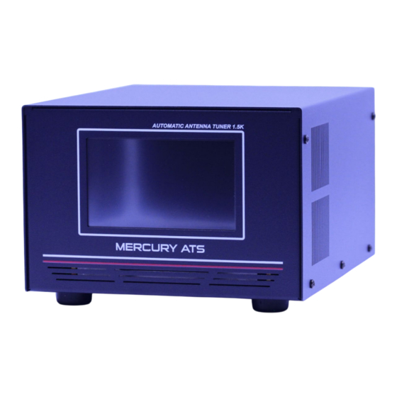
MERCURY ATS
Features
• Operating Bands 160m – 6m
• 5-inch Color Touch Screen
• FWD/REF/SWR Meter
• Selection for 3 Antennas
• 1-30 MHz 1500 watts SSB
• 1-30 MHz 1000 watts CW
• 1-30 MHz 700 watts DIGI mode
• 50 MHz 300 watts
• Inductance 6.3 uH / Capacitance 1100 pF
• Matching Range 5:1
• Tuned 1.5:1
• Minimum Tuner Level 10 Watts
• W 8 x L 10 x H 5.5 / Weigh 7.5 pounds
Automatic Antenna Tuner
Designed and Manufactured in the USA
Copyright 2023 KM3KM Electronics LLC.
OPERATION MANUAL V 1.0
Advertisement
Table of Contents

Related Manuals for KM3KM MERCURY ATS

Summary of Contents for KM3KM MERCURY ATS
- Page 1 • Matching Range 5:1 • Tuned 1.5:1 • Minimum Tuner Level 10 Watts • W 8 x L 10 x H 5.5 / Weigh 7.5 pounds Automatic Antenna Tuner Designed and Manufactured in the USA Copyright 2023 KM3KM Electronics LLC.
-
Page 2: Safety Warning
SAFETY WARNING Very high RF voltages, as well as large RF current flow, may be present in your MERCURY ATS. Like all antenna tuners meant for high power use, the MERCURY ATS handles a great deal of RF energy. Your MERCURY ATS is designed to safely handle this RF energy within its specifications, with a reasonable margin of safety. -
Page 3: Good Practice
GOOD PRACTICE Be sure to observe the MERCURY ATS specified power ranges. If the tuner fails due to overload, it could also damage your Transmitter or Amplifier. An antenna tuner transforms the impedance at the power point from the line to the equipment, to a value suitable for the transmitter, typically 50 Ohms. -
Page 4: Connections Diagram
Radio control interface (Optional) - 3.5 mm audio jack type to specific connector of transceiver to enable transceiver “tune” button. See page 7. Coax Jumper Cables - A Coax jumper of 2 feet or less from the amplifier to MERCURY ATS is recommended. -
Page 5: Main Screen
2 Reflected Power Indicator - Never operate ATS at more than 125 watts of reflected power. 3 Antenna Output Selectors - Select the button for antenna 1, 2, or 3. Antenna 1 will be connected if Mercury ATS is disconnected from 12 volts. The previous selection will remain in memory for the next power-up. -
Page 6: Setup Screen
Setup Screen 1. Beep - Disable the sound of buttons and confirmations. 2. Call Sign - Enter your Cal Sign to display on the main screen, up to 8 characters. 3. Auto - Enable and disable the Auto Tuner option. When SWR is above 1.8 the ATS will start the tuning process when RF is detected. -
Page 7: Rear View
Rear View 1. SO239 Input Connector. Connects the signal coming from the transceiver or amplifier. Do not connect Ferrite Clamp or RF Choke on this line. A Coax jumper of 2 feet or less from the amplifier to AT is recommended. 2.SO239 Output Connectors. -
Page 8: Tuning Guide
One of the following Banners will appear on the screen: The MERCURY ATS will calculate the loss and indicate if the tuning is appropriate to handle high power. -
Page 9: Radio Interface Configuration
RADIO INTERFACE CONFIGURATION The control connection from MERCURY ATS to your transceiver allows for an automatic tuning process when the TUNE button on the tuner or transceiver is pressed. The ATS sends a PTT signal (Active Low) into a tuner-dedicated port on the transceiver and the transceiver begins transmitting a low-level CW tone. - Page 10 IC-7000. IC-7600. IC-7300. IC-7610. IC-7700. IC-7100. IC-7200. IC-706. IC-707. IC-718. IC-725. IC-728. IC-736. IC-738. IC-746. IC-756. With most ICOM radios, RF power is lowered while MERCURY ATS is tuning. There is no need to change settings after or before tuning.
- Page 11 YAESU FT-891. FT-857D. FT-897D. FT-100. FT-100D. FT-991A With FT-991(A), go to menu 143 and select LAMP. For the FT-891, go to menu 16-15 and select LAMP. YAESU FTDX-101D. FTDX-101MP. FTDX-3000...
Need help?
Do you have a question about the MERCURY ATS and is the answer not in the manual?
Questions and answers