
Related Manuals for Oxford MULTIMIG CS273


Summary of Contents for Oxford MULTIMIG CS273
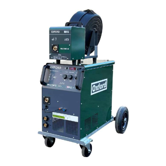
- Page 1 Oxford MULTIMIG CS range of Compact / Separate wire feed MIG welding machines Caution before installing or operating this machine ensure all instructions and warnings have been read and understood. INSTRUCTION MANUAL...
-
Page 2: Safety Guidelines
Safety Guidelines This machine is designed for use only by experienced operators only. All users must be competent, trained & familiar with welding processes and safe electrical practices. Before using this product, you should carry out a risk assessment & take appropriate action to minimize all risks. -
Page 3: Declaration Of Conformity
This equipment is manufactured to comply with 2006/95/EEC, BS EN 60974-1 This equipment is manufactured to comply with 89/336/EEC, BS EN 60974-10 This equipment is manufactured to RoHS directive 2006/95/EU Date 01/02/2023 R P Rycroft R Rycroft Oxford Welders, Technical Arc Ltd, York UK... - Page 4 MIG wire range 0.6-1.0mm 0.6-1.2mm 0.6mm-1.6mm 0.6mm-1.6mm Work lead (earth) Mains input lead 3M rubber 3M rubber 3M rubber 3M rubber Technical specifications Oxford MULTIARC CS single phase 230V models Model CS271 CS331 CS411 Supply voltage 230V 230V 230V Welding range (amps)
-
Page 5: Electrical Installation
Installation Unpacking - Check the packaging for any signs of damage. Carefully remove the machine and retain the packaging until the installation is complete. Assembling the machine For transportation, the wheels and bottle tray are not fitted to help prevent damage and make transporting easier. -
Page 6: Functions And Controls
Functions & Controls Euro torch connector – Connection for Mig torch. Welding positive Dinse connector – Connection for positive welding output. For standard MIG welding, plug the dinse plug from the torch into the positive dinse socket. For welding reverse polarity with flux cored wire etc, connect the dinse plug from the torch into the negative and the earth return lead into the positive dinse socket. - Page 7 Wire feed unit & inter connection lead The power source has the option to plug in the MULTIMIG 4X separate wire feed unit & inter-connection lead. This enables the operator to either keep the feeder on top of the power source or lift the wire feeder off and take closer to the work. The length of the inter connection lead is 5M as standard, but there is the option of fitting a longer inter-connection leads up to 20M.
- Page 8 Welding with this machine First ensure you are familiar with all risks & have taken necessary precautions. With the machine all set up ready to MIG weld, the operator should first set the welding power required to suit the thickness and type of weld to be carried out. As the welding power is adjusted the welding voltage selected is shown in the LED displayed.
- Page 9 MIG welding basics The normal process of MIG welding involves an electric arc, a consumable wire and a shielding gas. The electrical arc creates the heat which melts both the welding wire and the material being welded, the result is a weld pool which is protected from the atmosphere by the shielding gas, or by flux if using a special gas-less wire.
-
Page 10: Troubleshooting Guide
Trouble shooting guide Problem Machine stops welding after a period of use on higher settings but fan still runs. The display shows “F”. Solution Possible overheated internal components caused by duty cycle being exceeded, leave machine switch on for around half an hour & retry, ideally reduce output power or welding time to prevent re-occurrence. - Page 11 If correctly maintained this machine should give a long trouble free life. We aim to offer the very best long term support for your OXFORD machine. Your supplier should be able to organize all service, testing & supply of spares for this machine, if not please contact us directly at sales@oxfordwelders.co.uk.
- Page 12 Parts list – Power source CS 273 CS 333 CS 413 CS 513 CS 271 CS 331 CS 411 Part Part Part Part Part Part Part Description number number number number number number number Feed system FECX4002 FECX4002 FECX4002 FECX4002 FECX4002 FECX4002 FECX4002...
- Page 13 CS 273 CS 333 CS 413 CS 513 CS 271 CS 331 CS 411 Part Part Part Part Part Part Part Description number number number number number number number Large Side panel 1003105 1003105 1003105 1003105 1003105 1003105 1003105 Small side panel 1003106 1003106 1003106...
- Page 14 Parts list – 4x4 Wire feed system wear parts / electro mechanical D + E Description Part number pcs/machine Roller 0.6-0.8mm V groove for hard wire FECV0608 Roller 0.8-1.0mm V groove for hard wire FECV0810 Roller 1.0-1.2mm V groove for hard wire FECV1012 Roller 1.2-1.6mm V groove for hard wire FECV1216...
- Page 15 All spare parts are readily available from your local welding distributor. If overseas please contact the selling agent or contact us direct on sales@oxfordwelders.co.uk Manufactured in Great Britain by; Oxford Welders / Technical Arc Ltd York YO19 5UP Tel: 01904 410041 (International 0044 1904 410041)
Need help?
Do you have a question about the MULTIMIG CS273 and is the answer not in the manual?
Questions and answers