
Related Manuals for POSEIDON PE 250-HE


Summary of Contents for POSEIDON PE 250-HE
- Page 1 Instruction Manual High Pressure Breathing Air Compressors PE 250-HE PE 300-HE Copyright 2013 BAUER Kompressoren GmbH München...
- Page 3 Instruction Manual w Breathing Air Compressors INTRODUCTION This manual contains operating instructions and mainte nance schedules for the high pressure breathing air compres sors PE 320-HE WARNING ! Pneumatic high pressure system ! The breathing air produced with the compressor units de scribed in this manual is subject to strict quality standards.
- Page 4 Instruction Manual w Breathing Air Compressors TABLE OF CONTENTS 1. GENERAL ..................2.
- Page 5 See Chapter 8, Annex Lubricating oil list on CD Applicable parts list PE 250-HE, PE 300-HE TPEH-2/0 (on CD) Dear customer We are happy to give you advice on any questions regarding your BAUER compressor and help as soon as possible with any arising problems.
- Page 6 Instruction Manual w Breathing Air Compressors NOTES Model: Serial no.: Date of purchase: Dealer address/phone no.:...
- Page 7 Instruction Manual w Breathing Air Compressors GENERAL PURPOSE AND SHORT DESCRIPTION The PE 250-HE and PE 300-HE high pressure compressors are designed to compress air for breathing as required in div ing and fire fighting applications. The max. allowable operat...
- Page 8 Instruction Manual w Breathing Air Compressors • electric control system with automatic switch-off DESIGN AND MODE OF OPERATION Design Optional equipment: The compressor unit comprises the following major assem • Filter system P42 with or without SECURUS monitoring blies: device •...
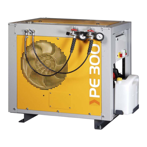
- Page 9 Instruction Manual w Breathing Air Compressors 1 Filling connector PN300 2 Filling pressure gauge 3 Phase-sequence warning light 4 Condensate tank 5 Stop button 6 Start button 7 Hour meter 8 Main switch Fig. 3 Compressor unit PE 300-HE, right side view 1 Filling pressure gauge 300 bar 2 Filling valve 300 bar 3 Safety valve 200 bar...
- Page 10 Instruction Manual w Breathing Air Compressors Compressor block IK120 These compressor blocks are particularly suitable for continuous operation because of their rugged design and The design of the compressor block is shown in Fig. 5. For the the corrosion resistant intermediate filter and cooler mode of operation refer to the flow diagram, Fig.
- Page 11 Instruction Manual w Breathing Air Compressors Air flow diagram See Fig. 6. The air is drawn in through intake filter -5, com filter assembly -12 which is fitted with a Triplex cartridge -17. pressed to final pressure in cylinders -1, -2, -3, and -4, and re The interfilters -10 and -11 and filter assembly -12 are cooled by inter-coolers -6, -7 and -8, and after-cooler -9.
- Page 12 Instruction Manual w Breathing Air Compressors TECHNICAL DATA Compressor unit PE 250-HE Compressor unit PE 250-HE-F02 Medium Breathing air Operating pressure PN 200 PN 300 Delivery 250 l/min. 250 l/min. Pressure setting, final pressure safety valve 225 bar 330 bar...
- Page 13 Instruction Manual w Breathing Air Compressors Compressor unit PE 300-HE Compressor unit PE 300-HE-F02 Medium Breathing air Operating pressure PN 200 PN 300 Delivery 300 l/min. 300 l/min. Pressure setting, final pressure safety valve 225 bar 330 bar Sound pressure level 87 dB(A) 87 dB(A) Sound power level...
- Page 15 Instruction Manual w Breathing Air Compressors SAFETY MEASURES 2.1. NOTES AND WARNING SIGNS 2.2. IDENTIFYING THE SAFETY NOTICES Important instructions concerning the endangerment of Notes and warning signs displayed on compressors personnel, technical safety and operating safety will be according to model, application or equipment. specially emphasized by placing the following signs before the instructions.
- Page 16 Instruction Manual w Breathing Air Compressors • Personnel may not wear long hair loose, loose clothing or • Observe switching on and off processes and monitoring jewellery, including rings. There is a danger of injury indications according to the instruction manual. •...
- Page 17 Instruction Manual w Breathing Air Compressors under the instruction and supervision of a qualified 2.3.6. Notices of danger regarding pressure vessels • Never open or loosen pressure vessel lids or pipe electrician according to electric technical regulations. • Machines and unit parts which must undergo inspection, connection parts under pressure;...
- Page 18 Instruction Manual w Breathing Air Compressors We recommend that aluminium vessels should be Copies of the above regulations are available through the exchanged after 15 years at the latest. usual outlets, e.g. in Germany from: Please pay attention to and follow these measures, for Carl Heymanns Verlag your own safety and that of you employees and Luxemburger Str.
- Page 19 Instruction Manual w Breathing Air Compressors INSTALLATION, OPERATION, FILLING PROCEDURE 3.1. INSTALLATION OF THE COMPRESSOR UNIT In the annex of this instruction manual you will find the standard schematic diagrams valid for the respective The compressor frame is equipped with anti-vibration compressor unit.
- Page 20 Instruction Manual w Breathing Air Compressors drain valves open, loosen screw (3, Fig. 7) on coil (1) and 3.5. FILLING PROCEDURE pull timer (2) from solenoid valve. General Ensure intake air is free from WARNING noxious gas (CO), exhaust fumes and solvent vapour.
- Page 21 Instruction Manual w Breathing Air Compressors security, the filling of breathing air bottles is not al Filling the bottles lowed in rooms used as workrooms. Open filling valve (1, Fig. 11). Scavenging the compressor unit Open bottle valve (2) - bottle will be filled. Drain conden sate regularly during filling.
- Page 22 Instruction Manual w Breathing Air Compressors Check the oil level in the compressor and top up, if service manual. necessary. Also check whether the compressor needs servicing in accordance with maintenance schedule - see 3.7. B-TIMER (optional) Introduction Read operating instructions carefully before operating the unit.
- Page 23 Instruction Manual w Breathing Air Compressors • Flashing last segment and change from operating hours in dication to cartridge part no. if capacity is equal or less than 20% of the original lifetime. • Indication of compressor maintenance due by means of letter symbols and operating hours.
- Page 24 Instruction Manual w Breathing Air Compressors Function Display To display the desired function, press the select key (=). Press = key. Remaining filter capacity is shown, Fig. 17) Press = key again. Remaining operating hours to service inter val A (500 hours or annually) are shown (Fig. 18). Fig.
- Page 25 Instruction Manual w Breathing Air Compressors Setup To enter the setup for the different functions of the B-Timer press the = and o keys on the display simultaneously for more than 5 seconds from the cartridge number display (Fig. 21). Filter symbol starts flashing (Fig.
- Page 26 Instruction Manual w Breathing Air Compressors MAINTENANCE 4.1. MAINTENANCE RECORD 4.4. MAINTENANCE WORK We recommend that all maintenance work is recorded in the This chapter contains the maintenance work as well as a service book delivered with every compressor unit, showing short functional description for each component.
- Page 27 Instruction Manual w Breathing Air Compressors Synthetic oils every 2,000 operating hours, at least biennially OIL CAPACITY Oil capacity approx. 2.8 liters OIL PACKAGES BAUER compressor oil is available in various quantities, refer to oil list in the annex. OIL CHANGE Run compressor warm.
- Page 28 Instruction Manual w Breathing Air Compressors Fig. 31 Intake filter Fig. 29 Removing the cover MAINTENANCE The filter cartridge must be cleanded or changed at regular intervals according to maintenance schedule in the service manual. Do not use any cleaning fluids which WARNING are a hazard to respiration.
- Page 29 Instruction Manual w Breathing Air Compressors operation of the unit to such a degree as to achieve four load CARTRIDGE SAFETY BORE cycles per hour, in our opinion this would be an optimum be The filter system P31 is designed to prevent pressurizing in tween usage and actual life.
- Page 30 Instruction Manual w Breathing Air Compressors GENERAL INSTRUCTIONS FOR FILTER MAINTENANCE Depressurize system before starting any maintenance work. Dry inside of filter housing with a clean cloth before in stalling new cartridge and check for corrosion. Change if necessary. Lubricate threads and O-rings as well as threaded part of cartridge with white petrolatum DAB 9 order no.
- Page 31 Instruction Manual w Breathing Air Compressors CARTRIDGE CHANGE Never remove replacement cartridge from packaging prior to actual use otherwise highly sensitive molecular sieve will ab sorb water vapour from surrounding air and cartridge saturated and thus be ruined. Depressurize filter system by opening condensate drain valves.
- Page 32 Instruction Manual w Breathing Air Compressors 1. Filter cartridge 80100: Filter cartridge lifetime [hours] Filling pressure p = 200 bar PE 250 PE 300 Ambient temperature Temperature of Flow capacity Flow capacity tU [°C] final separator Q [l/min] Q [l/min] tAb [°C] 20 - 24 48 - 38...
- Page 33 Instruction Manual w Breathing Air Compressors FILTER SYSTEM P42 (OPTION) PURPOSE AND SHORT DESCRIPTION Filter system P42 (Fig. 34) consists of: • Final separator, integrated in filter base part • Non-return valve between separator and purifier • High pressure purifier •...
- Page 34 Instruction Manual w Breathing Air Compressors cycles per hour, in our opinion this would be an optimum tables of the page 26 taking into consideration the ambient between usage and actual life. temperature and the cartridge used. To avoid exceeding the max. number of load cycles the These tables contain calculated cartridge lifetime data, that operating hours should be recorded in the service manual.
- Page 35 Instruction Manual w Breathing Air Compressors 1. Filter cartridge 062565: Filter cartridge lifetime [hours] Filling pressure p = 200 bar PE 250 PE 300 Ambient temperature Temperature of Delivery Delivery tU [°C] final separator Q [l/min] Q [l/min] tAb [°C] 20 - 24 125 - 99 104 - 83...
- Page 36 Instruction Manual w Breathing Air Compressors 4.5.4. FILLING VALVE MAINTENANCE Only carry out maintenance work on filling valves when the filling panel is depressuri zed. Filling valve with hand wheel To protect filling valve against contamination a sintered metal filter is screwed in the filling valve body. Unscrew pressure gauge (3, Fig.
- Page 37 Instruction Manual w Breathing Air Compressors 4.5.5. PRESSURE MAINTAINING VALVE 4.5.6. SAFETY VALVES DESCRIPTION DESCRIPTION A pressure maintaining valve is integrated in the P31 filter base (Fig. 39). All compressor stages are protected by safety valves. It ensures that pressure is built up in the filter even from the The safety valves are adjusted to the corresponding pressure start of delivery, thus achieving a constant, optimum filtra...
- Page 38 Instruction Manual w Breathing Air Compressors 4.5.7. PRESSURE GAUGE 4.5.8. VALVES FUNCTIONAL DESCRIPTION DESCRIPTION The valve heads of the individual stages form the top part of The compressor unit is equipped with a final pressure gauge the cylinders. The intake and pressure valves are fitted inside (Fig.
- Page 39 Instruction Manual w Breathing Air Compressors Lubricate valves before mounting with Weicon AS 040, 4.5.9. AUTOMATIC CONDENSATE DRAIN part no. N19753, or equivalent. DESCRIPTION The automatic condensate drain unit (Fig. 45) drains the Observe the correct sequence when fitting together intermediate separators and the oil and water separator again.
- Page 40 Instruction Manual w Breathing Air Compressors tervals. The maximum condensate level is marked with a black line. Due care must be taken to ensure that any oil which may be drained with the condensate will not pollute the environ ment. For example, the drain pipe can be directed into a col lecting vessel or into drain facilities incorporating oil separ...
- Page 41 Instruction Manual w Breathing Air Compressors 4.5.10. ELECTRICAL SYSTEM This section describes the standard electric control system of the compressor unit. The amount of built-in components varies depending on order. For schematic diagrams, see annex. The electrical equipment of the compressor unit consists of: •...
- Page 42 Instruction Manual w Breathing Air Compressors condensate drain interval is converted in a range setting turer and model, greasing of the bearings may be necessary. of 1.5 to 30 min. The setting of time is proportional: Observe respective notes on the motor. setting 15 sec in the time range 1.5...30 sec (preliminary CHECKING THE DRIVE BELT setting) becomes 15 min when changing the range to...
- Page 43 Instruction Manual w Breathing Air Compressors 4.5.12. COOLING SYSTEM GENERAL The cylinders of the compressor block, the intermediate coolers and the after-cooler are air-cooled. For this purpose, the compressor is equipped with a fan wheel. It draws the cooling air through the fanwheel cover from the surroundings.
- Page 44 Instruction Manual w Breathing Air Compressors 4.6. TROUBLE-SHOOTING Trouble Cause Remedy Drive motor (electric) Motor will not start Electric circuitry faulty Before attempting to make any repairs, check all fuses, terminal connections, wire leads, make sure that motor data complies with mains supply Drive system V−belt excessively worn out;...
- Page 45 Instruction Manual w Breathing Air Compressors Trouble Cause Remedy Automatic Condensate Drain (optional) Drain valves do not close No control air Check control air line Drain valves leaking Dismantle drain valve and clean Drain valves do not open Condensate drain valve piston jammed Dismantle drain valve, clean or replace valve Solenoid valve does not close Solenoid valve faulty...
- Page 46 Instruction Manual w Breathing Air Compressors STORAGE, PRESERVATION GENERAL PREVENTIVE MAINTENANCE DURING STORAGE If the compressor is put out of service for more than six Run the compressor once every 6 months as described in months, the unit should be preserved in accordance with the the following: following instructions: Remove the dust cap from the inlet port and insert the in...
- Page 47 Instruction Manual w Breathing Air Compressors REPAIR INSTRUCTIONS GENERAL Preventive maintenance usually involves replacing the valves, gaskets and sealing rings as well as carrying out the maintenance work. Repair work can be carried out on the compressor block to a certain extent but a certain experience and skill is necess ary.
- Page 48 Instruction Manual w Breathing Air Compressors TABLES TIGHTENING TORQUE VALUES TORQUE SEQUENCE Tighten valve head and cylinder bolts/nuts equally in the se Unless otherwise specified in text, the fol quence shown in Fig. 53. lowing torque values apply. All valve head screws require torque wrench tightening! Be sure to tighten all parts in cold condition only.
- Page 49 Instruction Manual w Breathing Air Compressors ANNEX • Air flow diagram Schematic diagrams Lubricating oil list Parts lists...
- Page 50 Instruction Manual w Breathing Air Compressors...
- Page 51 Air flow diagram...
- Page 52 Schematic diagram...
- Page 53 Components parts list Pos. Bezeichnung Designation Désignation Baugruppen Assemblies Assemblages Eingang, Kompressor Intake, compressor Entrée, compresseur BC2 Electronic Control BC2 Electronic Control BC2 surveillance électronique Umsetzer für eigensichere Stromkreise Converter for inherent circuits Convertisseur pour circuits auto-protégés Ansaugfilter, Mikronik Intake filter, micronic Filtre d'aspiration micronique BC6 Electronic Control BC6 Electronic Control...
- Page 54 Pos. Bezeichnung Designation Désignation Druckwächter bzw. -sensor, Ausgangsdruck Pressure switch or sensor, outlet pressure Manostat ou sonde, pression de sortie Pegelschalter, Öl Level switch, oil Interrupteur, niveau d'huile Druckwächter bzw. -sensor, Flaschendruck Pressure switch or sensor, bottle pressure Manostat ou sonde, pression des bouteilles Druckwächter bzw.
- Page 55 Pos. Bezeichnung Designation Désignation Düsen Nozzles Buses Düse, Steuermedium Nozzle, control medium Buse du milieu de commande Drossel Restrictor Soupape d'étranglement Meßgeräte Gauges Mètres Betriebsstundenzähler, Kompressor Hourmeter, compressor Compteur horaire, compresseur Spannungsmesser, Batterie Voltmeter Voltmètre, batterie Strommesser, Batterie Amperemeter Ampèremètre, batterie Tankanzeige Fuel gauge Jauge à...
- Page 56 Pos. Bezeichnung Designation Désignation Ventile, Hähne Valves and taps Vannes Füllventil, allgemein Filling valve, general Vanne de remplissage, général Füllventil, 200 bar Filling valve, 200 bar Vanne de remplissage, 200 bar Füllventil, 300 bar Filling valve, 300 bar Vanne de remplissage, 300 bar Abgangshahn Outlet valve Vanne de sortie...
Need help?
Do you have a question about the PE 250-HE and is the answer not in the manual?
Questions and answers