Advertisement
Quick Links
Humidifier
THESE INSTALLATION INSTRUCTIONS ARE FOR THE APRILAIRE® AUTOMATIC HUMIDIFIER CONTROL ONLY.
FOR APRILAIRE® HUMIDIFIER INSTALLATION, FOLLOW APRILAIRE HUMIDIFIER INSTALLATION INSTRUCTIONS.
WARNING
• ATTENTION INSTALLER: Read this manual before installing.
Improper installation or maintenance may cause property
damage or injury. It is recommended that installation, service,
and maintenance be performed by a trained service technician.
This product must be installed in compliance with all local, state,
and federal codes.
• ELECTRIC SHOCK HAZARD: 120 volts may cause serious injury from
electric shock. Disconnect electrical power to the HVAC system
and humidifier before starting installation or servicing. Leave
power disconnected until installation/service is completed.
CAUTION
SHARP EDGES MAY CAUSE INJURY FROM CUTS. Use care when
cutting plenum openings and handling ductwork. Always wear
glasses/goggles and gloves when installing the unit.
NOTICE
CONDENSATION DAMAGE OR MOLD CAN OCCUR.
• Do not set the humidifier control higher than recommended.
• Lower the humidity setting on the humidifier control if there is
excess condensation on the inside of any windows in unheated
living spaces.
CONTROLLER DAMAGE OR MALFUNCTION MAY OCCUR IF
INSTALLATION INSTRUCTIONS ARE NOT FOLLOWED.
• Install the humidifier control on return plenum only.
• Install the humidifier control upstream of the bypass outlet.
• Do not install the humidifier control facing downward.
• When installing the humidifier control on the return duct of a
downflow furnace, ensure the blower continues to run after
a heat call is satisfied to eliminate high temperatures from
damaging the humidifier control.
• Do not use solvents or cleaners on or near the display and circuit
board. Chemicals can damage components.
• Do not apply 120 VAC to the humidistat. The humidistat is
powered by 24 VAC. Disconnect power to the humidistat prior to
separating humidistat from its base.
SAFETY AND INSTALLATION INSTRUCTIONS
Model 56
Automatic Humidifier Control
STEP 1: UNPACK THE HUMIDIFIER CONTROL CARTON
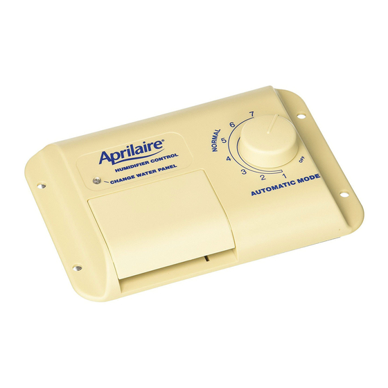
Make sure all components are present (see FIGURE 1).
A. Humidifier Control
B. Outdoor Temperature Sensor
C. Manual Mode Label
D. Manual Mode Resistor Case
WATER PANEL CHANGE INDICATOR
DOOR
STEP 2: DISASSEMBLE THE HUMIDIFIER CONTROL
Remove door from the Humidifier Control by pulling the bottom of the
door straight out.
STEP 3: CHECK THE MODE SWITCH
With the door removed, notice the switch labeled BYPASS and POWER
(partially covered by the enclosure). Use the following guide to
determine the correct setting for your humidifier model.
POWER SETTING: Models 110, 112, 445, 448, 760, 700 (almond-colored), 768,
800 (steam humidifier)
BYPASS SETTING: Models 220, 224, 400, 440, 500, 550, 558, 560, 568, 600,
700 (gray-colored)
FIGURE 1
D
C
A
B
90-1009
Product Info &
Digital Manual
Advertisement

Related Manuals for Aprilaire 56


Summary of Contents for Aprilaire 56
- Page 1 SAFETY AND INSTALLATION INSTRUCTIONS Model 56 Humidifier Automatic Humidifier Control THESE INSTALLATION INSTRUCTIONS ARE FOR THE APRILAIRE® AUTOMATIC HUMIDIFIER CONTROL ONLY. FOR APRILAIRE® HUMIDIFIER INSTALLATION, FOLLOW APRILAIRE HUMIDIFIER INSTALLATION INSTRUCTIONS. WARNING STEP 1: UNPACK THE HUMIDIFIER CONTROL CARTON Make sure all components are present (see FIGURE 1).
- Page 2 STEP 4: CHECK THE CHANGE WATER PANEL® INDICATOR SETTING STEP 8: ALTERNATE LOCATION FOR OUTDOOR TEMPERATURE SENSOR This setting will control when the indicator light turns on, reminding you to The Sensor can also be mounted in the center of either: change your water panel.
- Page 3 • If home is vacant, set Humidifier Control to OFF. Bypass and Power units are wired to the AHC in the same fashion. 8. Inform homeowner to refer to the AprilAire Owner’s Manual for the NOTE: This control does not support intelligent communication with other products.
- Page 4 • Call your installer to have your water panel changed, or visit your • If the humidity level in the home is less than the knob setting, the installer to purchase a new AprilAire water panel. Follow the instructions Humidifier Control will operate the Humidifier until the humidity level is on the water panel box.
Need help?
Do you have a question about the 56 and is the answer not in the manual?
Questions and answers