Advertisement
Quick Links
Advertisement

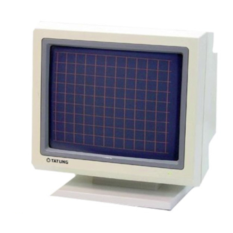
Summary of Contents for Tatung VM-14AF
- Page 1 VM-14AF SERVICE MANUAL...
-
Page 2: Table Of Contents
CONTENTS SPECIFICATION OPERATING INSTRUCTIONS IMPORTANT SAFEGUARDS ADJUSTMENT PROCEDURE BLOCK DIAGRAM SERVICE NOTES CIRCUIT DIAGRAM LAYOUT DIAGRAM EXPLODED DRAWING 10 PARTS LIST... -
Page 3: Specification
SPECIFICATION 14” Mono Chrome Monitor CRT SIZE 14” 90 DEGREES PHOSPHOR H68AU FACEPLATE NON-GLARE SCAN FREQ HOR. 31.5 KHz, 35.5 KHz, 35.2 KHz, 38 KHz VER. 40 – 75 Hz RESOLUTION 640 x 480, 800 x 600, 1024 x 768 BANDWIDTH 26 MHz, 35 MHz, 45 MHz VIDEO SIGNAL... -
Page 4: Operating Instructions
OPERATING INSTRUCTIONS POWER SWITCH Power on/off switch is a push button. To turn on the power of the unit, press this switch. To turn off the unit, press it again. POWER-ON INDICATOR The power-on indicator is lit when the power is turned on. BRIGHTNESS CONTROL Turn the brightness control clock-wise to increase the brightness and counter clock-wise to decrease it. -
Page 5: Important Safeguards
IMPORTANT SAFEGUARDS For your own safety read all instructions and retain them for further reference. POWER PLUG This display monitor is equipped with a 3-wire grounding type power plug. The third pin provides a safety ground for the display frame and will only fit into the power outlet of compatible configuration. - Page 6 INSTALLATION Do not place the display on an unstable cart, stand or shelf where it may fall and injure personnel or cause damage to the equipment. Install the unit on a solid firm base whenever possible. Route the power cord and all cables so they will not be walked on or tripped over.
-
Page 7: Adjustment Procedure
ADJUSTMENT PROCEDURE This alignment procedure is for adjusting/testing picture performance. In order to obtain the optimum result, the following adjustment sequence must be followed step by step: Check B+ voltage Test pattern: cross hatch Set up external brightness and contrast VR to central position Make sure 30Vdc = 0.1 Vdc use digital multimeter positive lead test D913 negative point, negative lead to ground. - Page 8 Vertical hold (Free-run 52Hz) adjustment: Disconnect video signal Use frequency counter O lead, measure vertical yoke point, adjustment VR302 make frequency value to 52Hz. Raster adjustment: Disconnect video signal Set up external brightness VR to maximum, external contrast VR to maximum Adjust VR403 have luminance equal to over 55FL 4-10 Brightness check: Test pattern: full white...
-
Page 26: Parts List
PARTS LIST LOCATION 010-3001-011 RESISTOR LOCATION LOCATION LOCATION R100 47R 011-0470-227 R221 62R 011-0620-227 R420 47K 011-0473-227 R101 47R 011-0470-227 R222 6K8 011-0682-227 R421 1K 011-0102-227 R102 330R 011-0331-227 R223 1K 001-0102-227 R422 013-0393-221 R103 330R 011-0331-227 R224 2K2 011-0222-227 R423 1K 011-0102-227 R104 75R... - Page 27 CAPACITOR LOCATION LOCATION LOCATION C100 47uf 050-4702-251 C309 .1 053-1045-500 C901 .22 070-2246-888 C101 .47uf 050-4792-501 C310 .1 053-1045-500 C903 4n7 071-4727-903 C102 100uf 050-1012-161 C311 47uf 050-4702-251 C904 4n7 071-4727-903 C103 10uf 050-1002-251 C312 .1 053-1045-500 C905 4n7 071-4727-903 C104 .1 053-1045-500 C313...
- Page 28 DIODE LOCATION LOCATION LOCATION D100 IN4148 117-0117-005 D203 IN4148 117-0117-005 D904 IN4007 119-1023-010 D101 IN4148 117-0117-005 D204 IN4148 117-0117-005 D905 BA159 119-1024-013 D102 IN4148 117-0117-005 D205 IN4148 117-0117-005 D906 PS104R 119-1023-018 D103 IN4148 117-0117-005 D300 IN4003 119-1023-009 D907 PS104R 119-1023-018 D104 IN4148 117-0117-005 D401 15QF6...
- Page 29 OTHER LOCATION LOCATION AC SOCKET ASSY 891-0030-001 USER MANUAL 312-0001-003 LED ASSY 891-0040-002 POWER CORD 400-0701-180 BASE ASSY 891-0050-002 SIGNAL CABLE 410-0101-150 500-5010-103 CARTON 305-1233-001 POLYFORM 460-0001-033 PE BAG 470-0010-001 P E BAG 470-0011-003...


Need help?
Do you have a question about the VM-14AF and is the answer not in the manual?
Questions and answers