Table of Contents

Related Manuals for GigE MotionBLITZ EoSens mini1


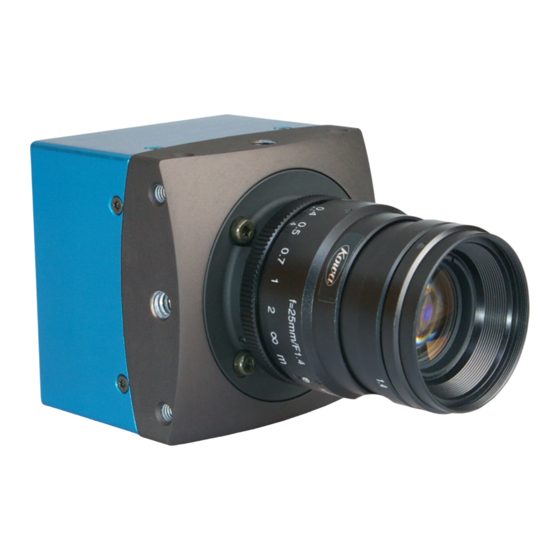
Summary of Contents for GigE MotionBLITZ EoSens mini1
- Page 1 MotionBLITZ® EoSens® mini1 Reference Guide CAMMC1370/71-RG Document version 2.0 Instrumentation Devices Srl Via Acquanera 29 - 22100 COMO (Italy) ph +39 031 525 391- fax +39 031 507 984 info@instrumentation.it - www.instrumentation.it...
-
Page 2: Table Of Contents
Contents Before you start About this manual 1.1.1 Tips, remarks, and notes 1.1.2 Registered trademarks 1.1.3 Conformity and use 1.1.4 Supplements Warranty and non-warranty clause Support Introduction to GenICam Overview Interface type Feature description Overview Device information 3.2.1 Overview 3.2.2 Controls Image size control 3.3.1... - Page 3 3.7.2 Controls Recording 3.8.1 Overview 3.8.2 Controls Streaming 3.9.1 Overview 3.9.2 Controls 3.10 CustomData 3.10.1 Overview 3.10.2 Controls 3.11 ImageBlitz 3.11.1 Overview 3.11.2 Controls 3.12 Synchronization 3.12.1 Overview 3.12.2 Controls 3.13 ExtTrigger 3.13.1 Overview 3.13.2 Controls 3.14 Multiple slope 3.14.1 Overview 3.14.2 Controls...
-
Page 4: Before You Start
Before you start This chapter provides the following information: About this manual Warranty and non-warranty clause Support... -
Page 5: About This Manual
Before you start About this manual This manual contains helpful information to install and operate the here described camera. It has been produced with care. Nevertheless, information might be erroneous or incomplete. Mikrotron GmbH cannot be held respons- ible for any problems resulting from incomplete or erroneous information. In case you detect errors or need further information, please inform us via mail: service@mikrotron.de... -
Page 6: Supplements
Before you start ments are designed to provide reasonable protection against harmful inter- ference when the equipment is operated in a commercial environment. This equipment generates, uses, and can radiate radio frequency energy and, if not installed and used in accordance with the instructions given in this guide, may cause harmful interference to radio communications. -
Page 7: Warranty And Non-Warranty Clause
Before you start Pour les utilisateurs au Canada Cet appareil est conforme aux normes Classe A pour bruits radioélectriques, spécifiées dans le Règlement sur le brouillage radioélectrique. Life support applications The products described in this manual are not designed for use in life support appliances or devices and systems where malfunction of these products can reasonably be expected to result in personal injury. -
Page 8: Support
Before you start Support 1. In case of support or a warranty claim, make a note of the camera type and its serial number (S/N). You find all necessary information on the iden- tification plate of the camera. 2. Contact us in one of the following ways: ... -
Page 9: Introduction To Genicam
Introduction to GenICam This chapter provides the following information: Overview Interface type... -
Page 10: Overview
Mikrotron EoSens mini1 & mini2 cameras are GigE Vision compliant. The GigE Vision standard uses Ethernet as the hardware interface to connect a camera to its host. GigE Vision is based on GEN<i>CAM and thus ensures compatibility to a wide range of programming interfaces and applications. -
Page 11: Interface Type
Introduction to GenICam Interface type Each feature is accessible via a specific interface and has a number of attrib- utes describing the current value / state and capabilities (e.g. value range) of a feature. The following interfaces are defined in the GenICam standard (each one is given with the typical widget used to map it on a graphical user inter- face). -
Page 12: Feature Description
Feature description This chapter provides the following information: Overview Device information Image size control Acquisition and trigger controls Analog controls UserSets Custom features Recording Streaming 3.10 CustomData 3.11 ImageBlitz 3.12 Synchronization 3.13 ExtTrigger 3.14 Multiple slope... -
Page 13: Overview
This section describes the camera features in detail. The method of reading and writing the features depends on the functions provided by the API of the GigE Vision SDK. Because the GigE Vision interface is standardized there are a number of different SDKs from different vendors able to communicate with the camera. -
Page 14: Controls
Feature description 3.2.2 Controls DeviceVendorName This feature provides the name of the manufacturer of the device. Access Read only Interface IString Unit Range Invalidation Precondition Note the string is limited by a trailing „\0“ DeviceModelName This feature provides the model of the device. Access Read only Interface... - Page 15 Feature description DeviceVersion This feature provides the version of the device. Access Read only Interface IString Unit Range Invalidation Precondition Note the string is limited by a trailing „\0“ DeviceID This feature stores a camera identifier. Access Read only Interface IString Unit Range...
- Page 16 Feature description DeviceScanType This feature specifies the scan type of the sensor. Access Read only Interface IEnumeration Unit Range Area Scan Invalidation Precondition Note DeviceReset When supported by the camera, this command resets the camera's circuitry. Access Write only Interface ICommand Unit Range...
-
Page 17: Image Size Control
Feature description Image size control 3.3.1 Overview Name Type Access SensorWidth Integer SensorHeight Integer SensorDigitizationTaps Enum WidthMax Integer HeightMax Integer Width Integer Height Integer PixelFormat Enum PixelCoding Enum PixelSize Enum PixelColorFilter Enum TestImageSelector Enum OffsetX Integer OffsetY Integer 3.3.2 Controls SensorWidth This feature indicates the effective width of the sensor in pixels. - Page 18 Feature description SensorHeight This feature indicates the effective height of the sensor in pixels. Access Read only Interface IInteger Unit pixel Range 1710 Invalidation Precondition SensorDigitizationTaps This feature represents the number of digitized samples outputted sim- ultaneously by the camera A/D conversion stage. Access Read / write Interface...
- Page 19 Feature description Access Read only Interface IInteger Unit pixel Range 1710 Invalidation Precondition Note Width This feature represents the actual image width expelled by the camera (in pixels). Access Read / write Interface IInteger Unit pixel Range 128...WidthMax - OffsetX, Inc. 16 Invalidates ...
- Page 20 Feature description PixelFormat This feature indicates the format of the pixel to use during the acquisition. Access Read only Interface IEnumeration Unit Range Mono8, BayerGR8 Invalidation Precondition Note Mono8: monochrome BayerGR8: color – Bayer Pattern coded PixelCoding This feature indicates the coding of the pixels in the image. The camera returns frame data in RAW format which is the native format of the sensor.
- Page 21 Feature description PixelColorFilter This feature indicates the type of color filter that is applied to the image. Access Read only Interface IEnumeration Unit Range None, BayerXX Invalidation Precondition Note None: monochrome BayerXX: Bayer Pattern Filter, XX order of the filters TestImageSelector This feature selects the type of test image that is expelled by the camera.
- Page 22 Feature description OffsetX This feature represents the horizontal offset from the origin to the AOI – Area Of Interest (in pixels). Access Read / write Interface IInteger Unit pixel Range 0...WidthMax - Width Invalidation AcquisitionFrameRateMax ExposureTimeMax RecordMaxFrames ...
-
Page 23: Acquisition And Trigger Controls
Feature description Acquisition and trigger controls 3.4.1 Overview NOTE Settings can only be changed if image acquisition is stopped. The following commands allow to make settings required for image acquis- ition and to control an external trigger. Name Type Access AcquisitionMode Enum AcquisitionStart... - Page 24 Feature description AcquisitionStart This feature starts the Acquisition of the device. Sending this command pre- pares the camera for image transmission to the host. The source of the images depends on the setting of the feature AcquisitionSource. If AcquisitionSource is set to Live streaming goes directly from the camera head to the hosts.
- Page 25 Feature description AcquisitionStop This feature stops the acquisition of the device at the end of the current Frame. If no acquisition is in progress the command is ignored. Access Write only Interface ICommand Unit Range Invalidation CameraState Precondition CameraState = Live or Recording or Streaming Note CameraState è...
- Page 26 Feature description ExposureMode This feature is used to set the operation mode of the exposure (or shutter). Cur- rently there is only timed exposure available. The exposure duration time is defined by the feature ExposureTimeAbs. Access Read / write Interface IEnumeration Unit Range...
-
Page 27: Analog Controls
Feature description AcquisitionSource This feature defines the source of image acquisition (live image or image from camera image buffer). Access Read / write Interface IEnumeration Unit Range Live, Memory Invalidation Precondition CameraState = Idle Note Live: Frame data is streamed directly from the camera to host without buffering. -
Page 28: Controls
Feature description 3.5.2 Controls GainRaw This feature controls the selected gain as a raw integer value. Access Read / write Interface IInteger Unit Range 100, 150, 200, 250, 300, 350, 400 Invalidation Precondition Note The value correspond with x1, x1.5, x2, x2.5, x3, x3.5, BlackLevelRaw This feature controls the analog black level as a raw integer value. -
Page 29: Usersets
Feature description UserSets 3.6.1 Overview The User Set feature is used to preserve current frame settings, even if the camera is switched off. The frame values that are stored are frame width, height, offset X and offset Y. The saved frame settings can be restored later by the user or if the camera gets reset by a power on / off cycle. - Page 30 Feature description UserSetLoad This feature loads the User Set specified by UserSetSelector to the device and makes it active. The User Set includes the features Width, Height, OffsetX, Off- setY. Access Write Interface ICommand Unit Range Invalidation Precondition UserSetSave This feature saves the current frame settings to the User Set specified by User- SetSelector.
-
Page 31: Custom Features
Feature description Custom features 3.7.1 Overview Name Type Access CameraState Enum ExtCameraID Integer Temperature Integer DecimationXY Boolean 3.7.2 Controls CameraState This feature returns the current transmission state of the camera. The camera always is in one of the following states: Access Read only Interface... - Page 32 Feature description ExtCameraID This feature describes the available options of the camera. Access Read Interface Unsigned 64 bit integer Unit Range 0 ... ffff ffff Invalidation Precondition CameraState = Idle The value of the feature has to be interpreted bit for bit: Bit No.
- Page 33 Feature description Bit No. Option Bit Value Description Standby (power supply with standby) Not used Power on recording Not used Not used Temperature This feature reads the temperature of the camera body as raw data. Access Read Interface IInteger Unit...
-
Page 34: Recording
Feature description Recording 3.8.1 Overview The cameras are equipped with an internal buffer of 2 to 4 GB that can be divided in 1, 2, 4, 8 or 16 sub buffers. The buffer is reserved to store sequences of images in the camera for later use. Recording to the camera internal memory can be done at full camera speed, which means 625 MB/s. -
Page 35: Controls
Feature description Name Type Access RecordTrailer Integer RecordMaxFrames Integer RecordNumberOfFramesPerSequence Integer RecordStop Command RecordStart Command 3.8.2 Controls RecordCameraBufferSize This feature returns the size of the camera internal image buffer in Giga Bytes. Access Read Interface IInteger Unit Giga Bytes Range Invalidation Precondition Note... - Page 36 Feature description RecordCurrentSequenceNumber If recording is running, this feature returns the number of the currently active sequence. Access Read Interface IInteger Unit Range 0 …16 Invalidation Precondition Note RecordBurstCnt This feature defines the number of consecutive frames to record after an external trigger or an image trigger occurs.
- Page 37 Feature description RecordStandby If this feature is True, the camera enters standby mode after next / current recording ends. In standby mode the camera is set to a state where it con- sumes as little current as possible. Only the part of the camera that is respons- ible for keeping the camera’s memory stable is kept active.
- Page 38 Feature description RecordNumberOfFrames This feature returns the number of recorded frames of all sequences. If record- ing is finished, this feature is set to the sum of all recorded images of all sequences. Access Read only Interface IInteger Unit number of pictures Range Invalidation Precondition...
- Page 39 Feature description RecordTrailer This feature defines the number of trailing frames to capture after recording stopped. This feature defines the number of frames to record after a record stop trigger is detected. The default value is 0. Access Read / write Interface IInteger Unit...
- Page 40 Feature description RecordNumberOfFramesPerSequence This feature returns the number of recorded frames per sequence. The sequence for which the number of recorded frames shall be returned must be selected by the feature ‘StreamSequenceSelector’ before reading (see feature category ‘Streaming’). Access Read only Interface IInteger Unit...
-
Page 41: Streaming
Feature description Streaming 3.9.1 Overview Streaming features are used to transfer previously recorded frames from the camera internal memory to the host computer. The camera can be configured to use 1, 2, 4, 8 or 16 different buffers (also called Sequences) for recording. The camera memory is divided by the number of sequences to record. -
Page 42: Controls
Feature description Name Type Access StreamSequenceSelector Integer StreamStartNumber Integer StreamEndNumber Integer 3.9.2 Controls StreamSequenceStart This feature starts streaming of a sequence of images. To prepare for stream- ing the feature AcquisitionSource must be set to Memory. The sequence from which we want to read the images must be selected by the feature StreamSequenceSelector. - Page 43 Feature description StreamSingleFrame This feature reads a single frame from an image buffer. The frame to read is absolutely addressed by its index in the sequence buffer. Before the image number is set, the feature AcquisitionSource must be set to Memory. The sequence the frame has to be read from must be selected by the feature StreamSequenceSelector.
- Page 44 Feature description StreamSequenceSelector This feature selects the current sequence for streaming. If streaming from the camera to the host is selected, this feature defines the index of the sequence the frames are read from. Access Read / write Interface IInteger Unit Range 0 ...
-
Page 45: Customdata
Feature description StreamEndNumber This feature defines the number of the end frame for reading frames from an image buffer. The index of the referenced streaming buffer must be selected by the feature StreamSequenceSelector before setting this parameter. The frame number is relative to each buffer. Access Read / write Interface... -
Page 46: Controls
Feature description 3.10.2 Controls Data00, Data01, Data02, Data03 Data00 to Data03 can be used to store custom data in the non-volatile memory of the camera. This preserves the data for later use, even if the camera power gets switched off. Access Read / write Interface... -
Page 47: Controls
Feature description Name Type Access IBWidth Integer IBOffsetX Integer IBHeight Integer IBOffsetY Integer IBEnable Boolean IBWindowVisible Boolean IBThreshold Integer IBReleaseCondition Integer 3.11.2 Controls IBWidth This feature defines the width of the ImageBlitz window in units of pixels. Access Read / write Interface IInteger Unit... - Page 48 Feature description IBHeight This feature defines the height of the ImageBlitz window in units of lines. Access Read / write Interface Integer Unit Range 1…SensorHeight-IBOffset, Inc. 1 Invalidation Precondition CameraState = Idle or Live IBEnable = True IBHeight*IBWidth <=20480 IBOffsetY This feature defines the offset of the ImageBlitz window starting from the first sensor line, in units of lines.
- Page 49 Feature description IBWindowVisible This feature displays or hides the ImageBlitz trigger window. The upper and lower border of the trigger window is displayed as dotted lines in each cap- tured image. Access Read / write Interface Integer Unit Range Invalidation Precondition CameraState = Idle or Live IBEnable = True...
-
Page 50: Synchronization
Feature description 3.12 Synchronization 3.12.1 Overview The cameras have an output pin that can be connected to a camera generated SYNC OUT signal or an ARM signal. If SYNC OUT is selected this output will carry a strobe that corresponds to the selected exposure time of the camera. If ARM is selected it will be active when the camera runs in circular recording mode. - Page 51 Feature description SyncOutSelect This feature defines the camera signal to connect to the Sync Out / ARM pin of the camera connector. Access Read / write Interface IEnum Unit Range ARM, SyncOut Invalidation Precondition CameraState = Idle Note ARM = Signals that the camera is in circular recording mode.
-
Page 52: Exttrigger
Feature description SyncInMode This feature defines how the sync in signal is used for image acquisition. Access Read / write Interface IEnum Unit Range Timer, PWC (= Pulse Width Control) Invalidation Precondition CameraState = Idle 3.13 ExtTrigger 3.13.1 Overview If the camera is in circular recording mode capturing frames can be stopped by a signal on the external trigger input pin of the camera. -
Page 53: Controls
Feature description 3.13.2 Controls ExtTriggerPolarity This feature defines if the camera trigger gets active on the rising or falling edge of the external trigger signal. Access Read / write Interface IEnum Unit Range Rising, Falling Invalidation Precondition CameraState = Idle ExtTriggerEnable This feature enables or disables the input port for an external trigger signal. -
Page 54: Controls
Feature description points within one frame time to reset over exposed pixels to a predefined value. Name Type Access MultipleSlopeMode Enum MultipleSlopeDualRaw Integer MultipleSlopeTripleRaw Integer 3.14.2 Controls MultipleSlopeMode This feature defines the Multiple Slope Mode. The multiple slope mode is used to extend the dynamic range of the camera. - Page 55 Feature description MultipleSlopeTripleRaw This feature sets the value for Triple Multiple Slope in percent of the exposure time. Access Read / write Interface Integer Unit Range MultipleSlopsDualRaw+1…99 Invalidation Precondition CameraState = Idle or Live and MultipleSlopsMode = TripleSlope Mikrotron GmbH / mini1 / CAMMC1370/71-RG / 2021 55 - 67...
-
Page 56: Programming
Programming This chapter provides the following information: Camera states State transformations Record programming Streaming programming ImageBLITZ programming... -
Page 57: Camera States
Programming Camera states The feature CameraState indicates the current state of the camera. The cam- era has 4 states: IDLE: the camera is in IDLE state LIVE: the camera is streaming live frames from the camera to the host ... -
Page 58: State Transformations
Programming State transformations The camera goes idle automatically after power-up. The diagram below shows the state transitions between the different camera states. Fig.: 4-1: Possible state transitions Transition Precondition Transition trigger IDLE ð LIVE AcquisitionSource = AcquisitionStart Live LIVE ð IDLE AcquisitionStop IDLE ð... -
Page 59: Record Programming
Programming Record programming 4.3.1 Overview The camera can save recorded frames directly into the internal memory of the camera at full speed. The memory can be configured as one large buffer or can be divided in up to 16 regions of equal size, called sequences. Recording is controlled by the features RecordStart, RecordStop and trigger signals. - Page 60 Programming The RecordMode and RecordNumberOfSequences, and RecordTrailer fea- tures must be set before recording is started. The value of the feature ‘RecordTrailer’ defines the number of additional frames to record after a stop signal is detected. The trailer value is only mean- ingful in continuous recording mode with one or more sequences.
-
Page 61: Continuous Recording - Multiple Sequences
Programming RecordMode = Continuous RecordNumberOfSequences = One RecordTrailer = (Range: 0..RecordMaxFramesPerSequence-1) RecordStart RecordStop or a trigger signal RecordTrailer unequal to 0, wait until the CameraState = Idle)(if it stops with a trig- ger signal, give the RecordStop) AcquisitionStop Read the RecordNumberOfFrames and RecordNum- berOfFramesPerSequence 4.3.3 Continuous recording - multiple sequences... -
Page 62: Single Recording
Programming Then the number of recorded frames can be read. You can read the sum of all recorded frames of all sequences (RecordNumberOfFrames) or the number of recorded frames in a specific sequence (RecordNum- berOfFramesPerSequence). To get the number of recorded frames in a spe- cific sequence, you have to select the sequence with the feature StreamSequenceSelector before. -
Page 63: Recordstandby (Usersets)
Programming RecordMode = Single RecordNumberOfSequences = One and unavailable (automatically) RecordWhileTriggerActive = True RecordBurstCnt = 0 RecordStart recording as long as trigger active wait recording as long as trigger active recording stops automatically (CameraState = IDLE), then RecordStop Read the number of recorded frames form the feature RecordNum- berOfFrames which should be equal to RecordNum- berOfFramesPerSequence. -
Page 64: Streaming Programming
Programming dependency of these values (e.g. RecordNumberOfFrames, RecordMaxFramesPerSequence, RecordMaxFrames, RecordNum- berOfFramesPerSequence). INFO It is good practice to save the current frame size of the camera to UserSet1 as soon as one of the parameters Width, Height, OffsetX or OffsetY gets changed if a recording shall be used after RecordStandby. -
Page 65: Frame Burst Mode
Programming 4.4.3 Frame burst mode In frame burst mode you can read a number of consecutive frames from the camera by defining a frame start number with the feature StreamStartNumber and the number of the last frame to be read by the feature StreamEndNumber. The address of the frame start number has to be less or equal than the frame end number. -
Page 66: Imageblitz Programming
Programming ImageBLITZ programming The patented ImageBLITZ® technology provides an extremely fast, accurate and sensitive trigger for image capture in high speed vision applications. The trigger event has to be unique so that it corresponds with a specific out- standing gray level change. Thus, the event can be identified by the ImageBLITZ sensitive line segment, making all elaborate sensing devices obsolete. - Page 67 Mikrotron GmbH Landshuter Straße 20-22 D-85716 Unterschleißheim / Germany Phone: 0049-089-7263420 www.mikrotron.de info@mikrotron.de © 04-2021 This document and the product(s) described are subject to change without fur- ther notice. Instrumentation Devices Srl Via Acquanera 29 - 22100 COMO (Italy) ph +39 031 525 391- fax +39 031 507 984 info@instrumentation.it - www.instrumentation.it...
Need help?
Do you have a question about the MotionBLITZ EoSens mini1 and is the answer not in the manual?
Questions and answers