Table of Contents
Advertisement
Quick Links
Advertisement
Table of Contents

Related Manuals for Norton clipper CT 601 B


Summary of Contents for Norton clipper CT 601 B
- Page 1 CT 601 B OPERATING INSTRUCTIONS Translation of the original instructions...
- Page 2 VERS.2023.02.28 CT 601 B_MAN_EN...
- Page 3 VERS.2023.02.28 CT 601 B_MAN_EN Declaration of conformity The undersigned manufacturer: SAINT - GOBAIN ABRASIVES S.A. 190, BD. J. F. KENNEDY L-4930 BASCHARAGE Declares that this product: CT 601 B 70184632582 Power Float: Code: is in conformity with the following Directives: •...
- Page 4 VERS.2023.02.28 CT 601 B_MAN_EN Declaration of conformity The undersigned manufacturer: SAINT - GOBAIN ABRASIVES S.A. 190, BD J.F. KENNEDY L- 4930 BASCHARAGE Declares that this product: 70184632582 Masonry Saw: CT 601 B Code: is in conformity with the following standard: •...
-
Page 5: Table Of Contents
VERS.2023.02.28 CT 601 B_MAN_EN CT 601 B OPERATING INSTRUCTIONS 1 BASIC SAFETY INSTRUCTIONS 1.1 Symbols 1.2 Machine plate 1.3 Safety instructions for particular operating phases 2 MACHINE DESCRIPTION 2.1 Short description 2.2 Purpose of use 2.3 Layout 2.4 Technical Data 2.5 Statement regarding the vibration emission 2.6 Statement regarding noise emission 3 ASSEMBLY AND COMMISSIONING... -
Page 6: Basic Safety Instructions
VERS.2023.02.28 CT 601 B_MAN_EN 1 BASIC SAFETY INSTRUCTIONS The CT 601 B is exclusively designed for the finishing of wet concrete floors mainly on construction sites. Uses other than the manufacturer's instructions shall be considered as contravening the regulations. The manufacturer shall not be held responsible for any resulting damage. Any risk shall be borne entirely by the user. -
Page 7: Machine Plate
Always use the machine with the safety guard ring, protection guards and electric box cover in position. • Only fit NORTON blades or plates to the machine! The use of other tools can damage the machine! • Attention is drawn to the use of BS2092 safety goggles in conformity with specified Processes No.8 of the Protection of Eyes Regulation 1974, Regulation 2(2) Part 1. -
Page 8: Machine Description
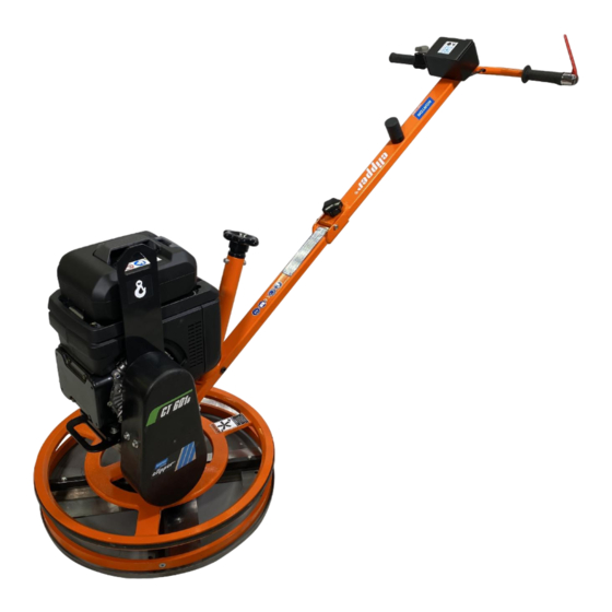
The Mechanical Trowel CT 601 B is designed for durability and high performance for onsite finishing operations on wet concrete floors. As with all other NORTON products, the operator will immediately appreciate the attention given to detail and quality of materials used in construction. The machine and its component parts are assembled to high standards assuring long life and minimum maintenance. - Page 9 VERS.2023.02.28 CT 601 B_MAN_EN Handle (1) Jig welded steel construction including 2 rubber grips. A dead-man handle (7) allows the operator to work safely and to stop the machine at any moment. The angle of the machine arm can be adjusted to operate the machine comfortably.
-
Page 10: Technical Data
VERS.2023.02.28 CT 601 B_MAN_EN 2.4 Technical Data Technical data Battery motor 1,8kW Max. tool diameter 600mm Rotation speed of the tool shaft 65-130 tr.min Sound pressure level 61,6 dB (A) (ISO EN 11201) Sound energy level 81,6 dB (A) (ISO EN 3744) Type of tool Blade or plate Machine dimensions (LxWxH) -
Page 11: Statement Regarding The Vibration Emission
VERS.2023.02.28 CT 601 B_MAN_EN 2.5 Statement regarding the vibration emission Declared value of vibration emission following EN 12096. Machine Measured value of vibration Uncertainty K Tool used Model / code emission at m/s Model / code CT 601 B <2.5 Original Pale 70184632582 •... -
Page 12: Statement Regarding Noise Emission
VERS.2023.02.28 CT 601 B_MAN_EN 2.6 Statement regarding noise emission Declared value of noise emission following EN ISO 11201 and NF EN ISO 3744. Machine Sound Uncertainty K Sound power Uncertainty K Model / code Pressure level (Sound level (Sound power level Pressure level EN ISO 11201 NF EN ISO 3744... -
Page 13: Assembly And Commissioning
3.1 Tool assembly Only NORTON blades or plate with a maximum diameter of 600 mm can be used with the CT 601 B. Before mounting a new tool into the machine, switch off the machine and isolate it from the main source of electricity. -
Page 14: Quick Reference Guide For Operation
VERS.2023.02.28 CT 601 B_MAN_EN 3.2 Quick reference guide for operation... -
Page 15: Battery Fixation And Starting The Machine
VERS.2023.02.28 CT 601 B_MAN_EN 3.3 Battery fixation and starting the machine • Set the machine arm in a comfortable position. To that purpose, loosen the handle on the arm and set the arm at a comfortable position, then retighten the handle. •... -
Page 16: Operating The Machine
VERS.2023.02.28 CT 601 B_MAN_EN 4 OPERATING THE MACHINE 4.1 Site of work • Remove from the site anything, which might hinder the working procedure! • Make sure the site is sufficiently well lit! • Observe manufacturer's conditions for connecting to power supplies! •... - Page 17 VERS.2023.02.28 CT 601 B_MAN_EN Handling the machine Operate the machine from right to left as shown in the following drawing: To move the machine: • Forward (I on the following drawing), turn the handle clockwise. • Backward (II), turn the handle counter clockwise. •...
-
Page 18: Transport And Storing
VERS.2023.02.28 CT 601 B_MAN_EN 5 TRANSPORT AND STORING 5.1 Securing for transport Before transporting the machine, always remove the blades and the plate. 5.2 Transport procedure Conform yourself to work regulations, in order to transport the machine safely. To lift the machine, use the lifting eye. Make sure that your lifting device is securely fastened to the lifting eye. -
Page 19: Maintenance And Servicing
VERS.2023.02.28 CT 601 B_MAN_EN 6 MAINTENANCE AND SERVICING To ensure a long-term quality from the use of the CT 601 B, please follow the maintenance plan below: Whole machine Visual control (general aspect, water tightness) Clean Surface of blades or plate Clean Tension of the blade Check... - Page 20 VERS.2023.02.28 CT 601 B_MAN_EN Maintenance du moteur...
-
Page 21: Faults: Causes And Cures
VERS.2023.02.28 CT 601 B_MAN_EN 7 FAULTS: CAUSES AND CURES Fault-finding procedures Should any fault occur during the use of the machine, turn it off, and isolate it from the electrical supply. Any works dealing with the electrical system or supply of the machine can only be carried out by a qualified electrician. -
Page 22: Customer Service
VERS.2023.02.28 CT 601 B_MAN_EN 7.3 Customer service When ordering spare parts, please mention: • The serial number (seven digits). • The code of the part. • The exact denomination. • The number of parts required. • The delivery address. • Please indicate clearly the means of transportation required such as "express"... -
Page 23: Spare Parts
VERS.2023.02.28 CT 601 B_MAN_EN Spare parts In order to consult the spare parts lists, we invite you to visit the after-sales website of Norton Clipper by using the following address: https://spareparts.nortonabrasives.com For a quick access, you can also use the QR Code shown below using your mobile phone: This electronic catalogue provides exploded views and spare parts lists for different machines designed by Norton Clipper so you can find references you need. - Page 24 VERS.2023.02.28 CT 601 B_MAN_EN...
Need help?
Do you have a question about the clipper CT 601 B and is the answer not in the manual?
Questions and answers