Table of Contents
Advertisement
Quick Links
Power Quality Recorder
15 Termo Lane, Techno Park, Stellenbosch, 7600, South Africa
Tel:
+27 21 880 9915
Fax:
+27 21 880 1088
Email:
info@ctlab.co.za
Web:
www.ctlab.com
All manuals and user guides at all-guides.com
Vecto
User Manual
Version 1.8
CT LAB (Pty) Ltd
PO Box 897, Stellenbosch, 7599, South Africa
© CT LAB (2018)
®
III
Advertisement
Table of Contents

Subscribe to Our Youtube Channel
Related Manuals for CT Lab Vecto III

Summary of Contents for CT Lab Vecto III
- Page 1 All manuals and user guides at all-guides.com ® Vecto Power Quality Recorder User Manual Version 1.8 CT LAB (Pty) Ltd PO Box 897, Stellenbosch, 7599, South Africa 15 Termo Lane, Techno Park, Stellenbosch, 7600, South Africa Tel: +27 21 880 9915 Fax:...
-
Page 2: Table Of Contents
Proprietary rights ....................10 1.4.3 Copyright ........................ 10 1.4.4 Trademarks ......................10 Introduction to the Vecto III 2.1 Vecto III Product Description ..............11 2.2 Receiving your Vecto III ................11 2.2.1 Receiving your shipment ................12 2.2.2 Unpacking the goods ..................13 2.2.3... - Page 3 2.3.10 Variable time interval trends ................ 20 2.3.11 Synchrophasors ....................20 2.3.12 Measured parameters ..................20 2.3.13 Technical Specification ..................24 2.4 Vecto III External Interfaces ..............27 2.4.1 Physical Appearance ..................27 2.4.2 Vecto III User Interface ..................29 2.4.3...
- Page 4 3.6 Error Conditions ..................48 3.6.1 Health Failure Conditions ................48 3.6.2 Recovery conditions ..................48 Vecto III Installation 4.1 Mounting the Vecto III ................50 4.1.1 Panel Mounting Installation ................50 4.1.2 19” Rack Mounting Installation ..............51 4.1.3 DIN rail mounting ....................
- Page 5 All manuals and user guides at all-guides.com 5.4.3 Sales Assistance ....................66 5.4.4 Repair and Calibration ..................66 5.4.5 Disposal........................67 Appendices Vecto III dimensions Vecto III wiring diagram Vecto III rating plate (Back plate) Accessories and Options Glossary Symbols and Abbreviations Vecto User Manual...
- Page 6 Figure 19: USB port ......................42 Figure 20: WIFI and Cellular Modem Connections ............43 Figure 21: Status LEDs, On/Off button and Power Button...........46 Figure 22: Vecto III back as supplied by CT Lab............50 Figure 23: Surface mount Vecto III ................50 Figure 24: 19’’ Plate Mounting..................51...
- Page 7 All manuals and user guides at all-guides.com Figure 25: Vecto III backside as shipped by CT Lab ............51 Figure 26: Vecto III back when Din rail mountings are to be used ......52 Figure 27: Vecto III AC power supply connection ............53 Figure 28: Vecto III single-phase connection ...............54...
-
Page 8: Safety Instructions
1 Safety Instructions This section provides information on safe handling, installation and commissioning of the Vecto III. Before carrying out any work on the equipment the user should be familiar with the contents of this document. Reference should be made to the instrument’s wiring diagram and the ratings before any installation can commence. -
Page 9: General Safety Information
The digital outputs can however be used for secondary protection functions. Vecto III is intended for indoor installation and use only. If it is required for use in an outdoor environment then it must be mounted in a specific cabinet or... -
Page 10: Statements And Notices
CT Lab (Pty.) Ltd., 15 Termo Lane, Techno Park, Stellenbosch 1.4.4... -
Page 11: Introduction To The Vecto
All manuals and user guides at all-guides.com 2 Introduction to the Vecto III This chapter introduce the Vecto III ®. The latest version of this document is shipped with the instrument but all new releases are available at www.ctlab.com. 2.1 Vecto III Product Description The Vecto III a comprehensive multi-function IEC 61000-4-30 Class power quality recorder with GPS-locked time synchronisation. -
Page 12: Receiving Your Shipment
Box has no water damage Inside Vecto III in a plastic enclosure Vecto III has no water damage or damp in the plastic enclosure Ethernet cable, Flash drive and the screw driver is included in the Vecto User Manual... -
Page 13: Unpacking The Goods
If the shipment is damaged or not in a working condition, please take a picture of the damage and send the pictures to info@ctlab.com as soon as possible. Please also phone CT Lab on +27 (21) 880 9915 to handle the problem as soon as possible. 2.2.2 Unpacking the goods Step... -
Page 14: Return Shipment
CT Lab. 2.3 Instrument Overview 2.3.1 Key Features The Vecto III records both voltages and currents of a single 3-phase feeder with IEC 61000-4-30 Class A performance. 1. Voltage inputs: Class A performance over all of the input range inclusive of 63.5 V (if L- N measurements are done in a 110 V line-line VT circuit) ... - Page 15 User-configurable triggering between different instruments: the patented Xross-Trigger feature (Described in the OspreyLite user manual) 9. Configuration of instrument The Vecto III has to be configured by means of an Ethernet connection to a local laptop with Osprey Lite installed. Vecto User Manual...
-
Page 16: Vecto Iii External Interfaces
Vecto III External Interfaces 2.3.2.1 Voltages The voltage inputs to the Vecto III interface directly to 110 V VT circuits or directly to a mains connection, which has to be less than 600 V line to neutral. Voltage measurements are differential. -
Page 17: Power Sources
2.4.13 for more information. The remote support software supports automatic service discovery protocols. Laptops, when connected to the Vecto III, will receive an IP from the instrument. The remote support software can automatically discover which instruments are connected to the local network. Please refer to the Osprey Lite user manual for more information. -
Page 18: Osprey Pro (Enterprise Support)
The 1/6 Sense The Vecto III calculates a complete set of 1-cycle sliding RMS and fundamental phasor parameters on each of the 3 voltage phases resulting in a resolution of 6 values per cycle per phase. The IEC 61000-4-30 Class A requirements are based on a ½... -
Page 19: Event Recording
10/12-cycle block and aggregated parameters. Single-phase and multiple-phase triggers can be defined. When a threshold is exceeded, the Vecto III will retain pre- and post-diagnostic information of the event. Please refer to the Osprey Lite user manual for more information on event recordings. -
Page 20: Variable Time Interval Trends
Clock synchronised parameters are time-stamped with a 1 second time resolution. 2.3.11 Synchrophasors The Vecto III is also a phasor measurement recorder. Recording of 50 Hz (or 60 Hz) synchrophasors can be activated in the configuration setup. Please refer to the Osprey Lite user manual for more information. - Page 21 All manuals and user guides at all-guides.com MEASURED PARAMETERS VOLTAGE ✓ ✓ ✓ Frequency (Hz) ✓ ✓ ✓ ✓ ✓ ✓ ✓ ✓ Voltage (Volt) ✓ ✓ ✓ ✓ ✓ ✓ ✓ Voltage (% of Nominal) ✓ ✓ ✓ ✓ Voltage (% of Fundamental) ✓...
- Page 22 All manuals and user guides at all-guides.com MEASURED PARAMETERS CURRENT ✓ ✓ ✓ ✓ ✓ ✓ ✓ ✓ Current (Ampere) ✓ ✓ ✓ ✓ ✓ ✓ ✓ Fundamental Current ✓ ✓ ✓ Current Phase Angle (Degrees) ✓ ✓ ✓ ✓ ✓...
- Page 23 All manuals and user guides at all-guides.com MEASURED PARAMETERS POWER ✓ ✓ ✓ ✓ ✓ ✓ ✓ Active Power (Watt) ✓ ✓ ✓ ✓ ✓ ✓ ✓ Reactive power (VAR) Apparent Power (VA) ✓ ✓ ✓ ✓ ✓ ✓ ✓ ✓...
-
Page 24: Technical Specification
All manuals and user guides at all-guides.com 2.3.13 Technical Specification VOLTAGE INPUTS Number of channels 4 x differential inputs (3/4 Wire + 4 Diff) Measurement input range 0 – 600 V ), 0 – 1000 V Voltage measurement Single Phase, 3-Phase (Star, Delta), DC Input impedance/channel >... - Page 25 All manuals and user guides at all-guides.com Switch Rating 0.1 A , 300 V (max) ACCURACY & BANDWIDTH Power frequency range DC, 50 H (40-60 Hz), 60 Hz (50-70 Hz) Harmonic bandwidth 1-64 (harmonic and inter-harmonic) Measurement sampling rate 0.5 MHz (simultaneously sampled) Waveform storage rate 1 kHz –...
- Page 26 All manuals and user guides at all-guides.com AC / DC supply voltage input 90-300 V 42-69 Hz (power factor corrected) range Power over Ethernet IEEE 802.3 compliant (35-60 V On-board battery LiFePO (2,000 charge/discharge cycles) PHYSICAL Construction Aluminium, 250 x 135 x 65 (L x W x H) Mounting options 3U-19”...
-
Page 27: Vecto Iii External Interfaces
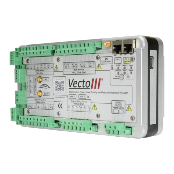
2.4.1 Physical Appearance Figure 3 shows the front of the Vecto III. The nameplate displays the name and serial number of the instrument, detail layout of the external interfaces of the instrument and instrument power and On/Off switches. A detail description of the external interfaces is provided in Sections 2.4.2 to 2.4.11. -
Page 28: Figure 4: Back Of Instrument
All manuals and user guides at all-guides.com a) Investigation instrument rubber foot piece b) Surface mount installation Surface mounting plates c) DIN rail installation DIN rail mounting set Figure 4: Back of instrument Vecto User Manual... -
Page 29: Vecto Iii User Interface
2.4.3 Power Supply The Vecto III can be powered and charged directly from mains (90 – 300 V AC/DC) via a power factor corrected internal power supply. The Vecto III can also be powered and charged via an IEEE 802.3-2008 compliant Power over Ethernet (PoE) power supply. -
Page 30: Figure 7: Vecto Iii Power Supply Connection
The supply current is power factor corrected and the maximum power consumption of the Vecto III is actively limited to 12.5 VA. The Vecto III can be powered directly from 110 V 50/60 Hz VT circuits due to this low burden. -
Page 31: Figure 8: Ethernet Ports
Vecto III will automatically disconnect from mains if excessive current is drawn from the universal AC/DC supply input port. When this protection was activated, it needs a few minutes to cool, during which the Vecto III will not restart even with valid mains voltage. -
Page 32: Voltage Inputs
All manuals and user guides at all-guides.com 2.4.4 Voltage Inputs The Vecto III has 4 resistive differential voltage inputs made up of 6 terminals. The first 4 terminals are used for 3 voltage inputs. V and V are Neutral (V... -
Page 33: Figure 9: Vecto Iii 4-Wire Star Connection
All manuals and user guides at all-guides.com Figure 9: Vecto III 4-wire star connection Figure 10: Vecto III 3-wire delta connection Vecto User Manual... -
Page 34: Current Inputs
2.4.5 Current Inputs The Vecto III has 4 galvanically isolated resistive current shunt inputs with input impedance of 20 m and a full-scale measurement range of 6 A AC-RMS Resistive shunts provide excellent AC and DC response; zero offset drift and very low temperature drift. -
Page 35: Figure 11: Current Sensor Connection
All manuals and user guides at all-guides.com Table 3: Current sensor connection layout Terminal Legend Description Phase 1 Current Input Phase 1 Current Return Phase 2 Current Input Phase 2 Current Return Phase 3 Current Input Phase 3 Current Return Phase 4 Current Input Phase 4 Current Return Figure 11: Current sensor connection... -
Page 36: Current Transducer Inputs
CT circuits and can only be done by an appointed and certified electrician 2.4.6 Current Transducer Inputs The Vecto III has 4 voltage-output current transducer inputs with a full-scale rating of 1.4 V . These voltage inputs can be used to directly interface with voltage-output AC-RMS current sensors such as Hall-effect devices and Rogowsky coils. -
Page 37: Relay Outputs
All manuals and user guides at all-guides.com Table 4: Current transducer connection layout Terminal Legend 1V Output Current Transducer Circuits CT 1 - V Voltage 1 CT 1 - +5V 5 V Power Supply CT 1 - V Voltage 1 Reference CT 2 - V Voltage 2 CT 2 - +5V... -
Page 38: Digital Inputs
All manuals and user guides at all-guides.com Figure 13: Relay switch connection layout Table 5: Relay switched outputs layout Terminal Legend Description OUT1 Switch 1 OUT1 Switch 1 OUT2 Switch 2 OUT2 Switch 2 OUT3 Switch 3 OUT3 Switch 3 OUT4 Switch 4 OUT4... -
Page 39: Figure 14: Digital Inputs Connection Layout
All manuals and user guides at all-guides.com connector plug with screw terminals. Each terminal can accommodate conductors with size up to 2.5mm Figure 14: Digital inputs connection layout Terminal Legend Description Input 1 Input 2 +5 V Input A – 5 V Supply Input A - Common Input 3 Input 4... -
Page 40: Figure 15: Digital Input Configuration For A Dry Contact
All manuals and user guides at all-guides.com Figure 15: Digital input configuration for a dry contact Figure 16: Digital input configuration for a wetted contact Vecto User Manual... -
Page 41: Gps
The female SMA port is used to interface an external powered (+3V3) GPS antenna to the Vecto III. The built-in GPS is used to measure absolute time. The Vecto III locks its internal clock to within 1µs from absolute time. -
Page 42: Usb Peripheral Port
2 IEEE 802.3-2008 compliant Power over Ethernet (PoE) is available on both Ethernet ports. The PoE capability enables the Vecto III to be powered through the communication infrastructure. The Vecto III will therefore be available at all times while the communication infrastructure stays on-line. -
Page 43: Wifi
WIFI without the antenna connected may cause damage to the device. 2.4.13 Built-in GPRS Modem (Optional) The Vecto III can be shipped with a built-in modem (see Figure 20). Please refer to the Osprey Lite user manual for instructions on configuring modem communication. -
Page 44: Operating Instructions
Section 0). In this mode the built-in RTC, the PDU and the health sensors are powered. When the Vecto III will not be used for an extended period of time it can be put into storage mode. To place the instrument is in storage mode the Power button is toggled off (not depressed). - Page 45 All manuals and user guides at all-guides.com Note that removing power from the instrument also removes power from the real- time clock (RTC). Upon start-up after a power cycle the RTC is in an unknown state and the instrument must first be connected to a valid time source (GPS or NTP) to ensure it time-stamps data correctly.
-
Page 46: Interpretation Of Status Leds
All manuals and user guides at all-guides.com 3.3 Interpretation of Status LEDs Name Function Power Briefly flashes periodically while the instrument is ready to run Charge On while charging the battery, off otherwise Ext Power On when the instrument receives power from an external source, off otherwise Green The instrument is synchronised to GPS... -
Page 47: Powering Up The Vectoii
All manuals and user guides at all-guides.com 3.4 Powering up the VectoII The following two sections describe the method for powering up the Vecto III. After powering up the instrument the Status LED will be flashing green. Osprey Lite be now used to configure the instrument (please refer to Osprey Lite User manual for more detail). -
Page 48: Error Conditions
3.6.2 Recovery conditions The Vecto III continuously performs internal health checks. Should one of these checks fail, the device will attempt to recover itself. In case the battery voltage or temperature readings exceed operating limits, the device will perform a controlled shutdown which is indicated by an orange Status LED. - Page 49 On/Off button. Please contact CT LAB for support if this state is encountered and not cleared by switching the instrument to storage mode and back to ready mode.
-
Page 50: Vecto Iii Installation
4.1.1 Panel Mounting Installation Figure 22: Vecto III back as supplied by CT Lab Unscrew the Allen-key screw shown in Figure 22 and turn the installation plates to the outside and shift hole 1 to 2. This should leave the installer with surface mounting holes, as indicated in Figure 23, to install the instrument on the required surface. -
Page 51: 19" Rack Mounting Installation
A 19” rack (4U) stainless steel mounting plate secures the Vecto III and provides a mechanical interface for 19” racks The 19” plate and the Vecto III is shipped separate and must be assembled on site. Step 1: Change the Vecto III configuration to panel mounting configuration as described in section 4.1.1. -
Page 52: Connections
Unscrew the Allen-key screw shown in Figure 25 and turn the installation plates over as indicated. The Din rail mounting is in a Vecto III cavity and will be available for use when the installation plates are turn over as shown in Figure 26. -
Page 53: Power Over Ethernet
All manuals and user guides at all-guides.com Figure 27: Vecto III AC power supply connection 4.2.2 Power Over Ethernet In addition to, or as alternative to AC power, the instrument can be powered via any of the Ethernet ports using an IEEE 802.3-2008 compliant power source (48 V). -
Page 54: Figure 28: Vecto Iii Single-Phase Connection
Connect the phase Voltage to Voltage Inputs 1 as shown in Figure 28. Connect Neutral (on 400 V systems) or the star-point (on 110 V VT circuits) to The fourth voltage input may be used to measure Neutral-Earth voltage. Figure 28: Vecto III single-phase connection Vecto User Manual... - Page 55 All manuals and user guides at all-guides.com 4.2.3.2 110 V Voltage Transformer (VT) Circuits & 400 V Direct (Star/ 4-wire systems) Always connect the safety earth terminal located on the power connector first Table 10: VT circuit connection layout for 4-wire star connection Terminal Legend 110V VT Circuit or 400V/550V Star (4-wire) Systems...
-
Page 56: Figure 29: Vecto Iii 4-Wire Star Connection
All manuals and user guides at all-guides.com Figure 29: Vecto III 4-wire star connection 4.2.3.3 110V Voltage Transformer (VT) Circuits or 400V/550V Direct (Delta/3- wire systems) Always connect the safety earth terminal located on the power connector first Vecto User Manual... -
Page 57: Figure 30: Vecto Iii 3-Wire Delta Connection
1) Connect Phase 1,2 and 3 to Voltage Inputs 1-3 as shown in the Figure 30. 2) Leave V open or connect V to the earthed Phase (Phase 2) on 110 V VT circuits. Figure 30: Vecto III 3-wire delta connection Vecto User Manual... -
Page 58: Current Connections
Direct (1 A/5 A Current Transformer (CT) Circuits) 4.2.4.1.1 Single phase connection The Vecto III can interface with 1 A or 5 A CT circuits and has a peak long-term current withstand of 6 A and 50 A for 3 seconds. Table 12: CT circuit connection layout... -
Page 59: Figure 31: Ct Circuit Connection Layout
Figure 31: CT circuit connection layout 4.2.4.1.2 Three-phase connection The Vecto III can interface with 1 A or 5 A CT circuits and has a peak long-term current withstand of 6 A and 50 A for 3 seconds. Table 13: CT circuit connection layout... -
Page 60: Figure 32: Ct Circuit Connection Layout
All manuals and user guides at all-guides.com Figure 32: CT circuit connection layout The Vecto III can be configured to: Derive the Neutral current by the summation of the 3 line currents in star connected (4-wire) circuits. Derive any one of the missing line currents by the summation of the other 2 currents in Delta connected (3-wire) circuits. -
Page 61: Figure 33: Ct Circuit Connection Layout
All manuals and user guides at all-guides.com Table 14: Current transducer sensor connection layout Terminal Legend 1 V Output Current Transducer Circuits Voltage 1 Voltage 1 Reference None None None None None None Phase 1 5V Power Phase 1 Ref Figure 33: CT circuit connection layout Vecto User Manual... -
Page 62: Figure 34: Ct Circuit Connection Layout
All manuals and user guides at all-guides.com 4.2.4.2.2 Three-phase connection The current transducer input on the Vecto III has a peak voltage input range of 2 V (1.4 V Table 15: Current transducer sensor connection layout Terminal Legend 1V Output Current Transducer Circuits... -
Page 63: Ethernet Based Communication
All manuals and user guides at all-guides.com The Vecto III can be configured to: Derive the Neutral current by the summation of the 3 line currents in star connected (4-wire) circuits. Derive any one of the missing line currents by the summation of the other 2 currents in Delta connected (3-wire) circuits. -
Page 64: Maintenance
All manuals and user guides at all-guides.com 5 Maintenance The Vecto III is designed to be a very low maintenance that can operate unattended for years. It contains no user-replaceable parts. 5.1 Battery The internal LiFePO battery powers the instrument in the absence of power. This battery guarantees 2,000 charge/discharge cycles. -
Page 65: Warrantee And Repair
Warrantee Statement CT Lab (Pty.) Ltd. Warrants its products and parts as set forth below. Please note that this is only applicable if the product is bought directly from CT Lab (Pty.) Ltd. or CT Lab (Pty.) Ltd. accredited resellers. -
Page 66: Technical Support
(including as a result of modifications required by CT Lab (Pty.) Ltd.); converted; altered; damaged; read by equipment not approved by CT Lab (Pty.) Ltd. If CT Lab (Pty.) Ltd. identifies any exceptions during examination, troubleshooting or performing any type of support on behalf of Customer, then Customer shall pay for and/or reimburse CT Lab (Pty.) Ltd. - Page 67 The WEEE Directive outlines the procedure for handling electrical waste equipment across the EU. The Vecto III may not be disposed of with normal waste. Should the Vecto III reach its end of life, the instrument may be returned to the distributor free of charge. In addition, CT LAB will accept instruments that reached end of life free of charge.
- Page 68 Please ensure you dispose of electrical devices in accordance with the valid regulations in your country. CT LAB will accept instruments that reached end of life free of charge.
- Page 69 All manuals and user guides at all-guides.com Appendices 1 Vecto III dimensions Vecto User Manual...
- Page 70 All manuals and user guides at all-guides.com 2 Vecto III wiring diagram Vecto User Manual...
- Page 71 All manuals and user guides at all-guides.com 3 Vecto III rating plate (Back plate) Vecto User Manual...
- Page 72 All manuals and user guides at all-guides.com 4 Accessories and Options The following are standard options. Vecto III - Panel mount or Din-Rail Vecto III GPS antenna & 15m extension cable GPS antenna mounting bracket GPS antenna...
- Page 73 GPS antenna 15m extension cable GPS antenna mounting plate bracket Screw driver USB with meter key Ethernet cable Vecto III – Portable unit Vecto III Portable Vecto III case GPS anteanna + 15m extension cable WIFI Antenna ...
- Page 74 All manuals and user guides at all-guides.com Portable case Magnetic GPS antenna 15m extension cable Voltage connection wiring Voltage connection clips Current connection wiring US clamps 250/500/1000:5A CT Micro clamps 5A:1V Pic-tails for safe connection to the Impedo DUO Vecto User Manual...
- Page 75 All manuals and user guides at all-guides.com Screw driver USB with meter key Ethernet cable Vecto User Manual...
- Page 76 All manuals and user guides at all-guides.com 5 Glossary Instrument – Electronic device, such as the Vecto III Meter – Component of an instrument that performs measuring (the Vecto III contains two meters) Meter Point – The physical measuring point that is...
- Page 77 All manuals and user guides at all-guides.com 6 Symbols and Abbreviations User Interface Graphical User Interface Power Quality Network Time Protocol Precision Time Protocol Real-Time Clock Parts Per Million Power Distribution Unit Voltage Transformer Current Transformer Root Mean Square Total Harmonic Distortion Vecto User Manual...
Need help?
Do you have a question about the Vecto III and is the answer not in the manual?
Questions and answers