Sign In
Upload
Manuals
Brands
CT Lab Manuals
Data Loggers
Vecto III
CT Lab Vecto III Power Quality Monitoring Manuals
Manuals and User Guides for CT Lab Vecto III Power Quality Monitoring. We have
2
CT Lab Vecto III Power Quality Monitoring manuals available for free PDF download: User Manual
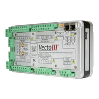
CT Lab Vecto III User Manual (80 pages)
Multi-function Power, Power Quality and Micro Synchrophasor Recorder
Brand:
CT Lab
| Category:
Measuring Instruments
| Size: 2 MB
Table of Contents
Table of Contents
2
Safety Instructions
8
Symbols
8
Safety Standards Compliance
9
General Safety Information
9
How to Mitigate Risks
11
Always Earth the Device First
11
Install External Shorting Blocks
11
Locking of Terminal Plugs
11
Use of External Fuses or Circuit Breakers
11
Provide Surge Arrestors
11
Statements and Notices
12
Statement of Reliability
12
Proprietary Rights
12
Copyright
12
Trademarks
12
Figure 1: Front View of the Vecto III Device
12
Introduction to the Vecto
13
Vecto III Product Description
13
Receiving Your Vecto III
13
Figure 2: Packaging Opened
13
Receiving Your Shipment
14
Unpacking the Goods
14
Checking the Battery Level
14
Return Shipment
15
Device Overview
16
Key Features
16
Vecto III External Interfaces
18
Power Sources
18
Communication
19
Built-In HMI (Web Interface)
19
Osprey Pro (Enterprise Support)
19
Sampling Rate
20
The 1/6 Th Sense
20
Event Recording
20
10/12-Cycle Block Recording
21
Variable Time Interval Trends
21
Synchrophasors
21
Trended RMS & Fundamental Parameters
22
Trended Power Parameters
24
Trended Individual Harmonic/Interharmonic Parameters
25
Technical Specification
26
Vecto III External Interfaces
29
Physical Appearance
29
Figure 3: Front View of the Vecto III Device
29
Figure 4: Rear View of the Vecto III Device
30
Vecto III User Interface
31
Power Supply
31
Figure 5: Right-Hand View of the Vecto III Device
31
Figure 6: User Interface
31
Figure 7: Vecto III Power Supply Connection
32
Figure 8: Ethernet Ports
33
Voltage Inputs
34
Figure 9: Vecto III 4-Wire Star Connection
35
Figure 10: Vecto III 3-Wire Delta Connection
35
Current Inputs
36
Figure 11: Current Sensor Connection
37
Current Transducer Inputs
38
Figure 12: Current Transducer Connection
38
Relay Outputs
40
Figure 13: Relay Switch Connection Layout
40
Digital Inputs
41
Figure 14: Digital Inputs Connection Layout
41
Figure 15: Digital Input Configuration for a Dry Contact
42
Figure 16: Digital Input Configuration for a Wetted Contact
42
Gps
43
Ethernet Ports
43
Figure 17: GPS Antenna Connector
43
USB Peripheral Port
44
Figure 18: Ethernet Ports
44
Figure 19: USB Port
44
Wifi
45
Built-In GPRS Modem (Optional)
45
Firmware
45
Upgrading
45
Figure 20: Wifi and Cellular Modem Connections
45
Operating Instructions
46
Precautions When First Using the Device
46
Toggling Storage/Ready Mode
46
Interpretation of Status Leds
47
Powering up the Vecto III Device
48
Powering up from Storage Mode
48
Powering up from Ready Mode
48
Figure 21: Status Leds, On/Off Button and Power Button
48
Shutting down
49
HMI (Web Interface)
49
HMI Features
50
HMI User Documentation
50
Error Conditions
51
Health Failure Conditions
51
Recovery Conditions
51
Vecto III Installation
52
Mounting the Vecto III
52
Panel Mounting Installation
52
Figure 22: Vecto III Back as Supplied by CT LAB
52
19" Rack Mounting Installation
53
Figure 23: Surface Mount Vecto III
53
Figure 24: 19'' Plate Mounting
53
DIN Rail Mounting
54
Connections
54
AC Power
54
Figure 25: Vecto III Rear View as Shipped by CT LAB
54
Figure 26: Vecto III Rear View When Din Rail Mountings Are to be Used
54
Power over Ethernet
55
Voltage Connections
55
Figure 27: Vecto III AC Power Supply Connection
55
Figure 28: Vecto III Single-Phase Connection
56
Figure 29: Vecto III 4-Wire Star Connection
58
Figure 30: Vecto III 3-Wire Delta Connection
59
Current Connections
60
Figure 31: CT Circuit Connection Layout
60
Figure 32: CT Circuit Connection Layout
61
Figure 33: CT Circuit Connection Layout
63
Figure 34: CT Circuit Connection Layout
64
Ethernet Based Communication
65
Gps
65
Wifi
65
Modem
65
Maintenance
65
Battery
65
Transport
65
Storage
66
Warrantee and Repair
66
Warrantee Statement
66
Technical Support
67
Sales Assistance
68
Repair and Calibration
68
Disposal
69
Appendices
70
Vecto III Dimensions
70
Vecto III Wiring Diagram
71
Vecto III Top View
72
Vecto III Purchase Options
73
Glossary
79
Symbols and Abbreviations
80
Advertisement
CT Lab Vecto III User Manual (77 pages)
Power quality recorder
Brand:
CT Lab
| Category:
Measuring Instruments
| Size: 3 MB
Table of Contents
Table of Contents
2
Safety Instructions
8
Symbols
8
Safety Standards Compliance
8
General Safety Information
9
Statements and Notices
10
Statement of Reliability
10
Proprietary Rights
10
Copyright
10
Trademarks
10
Introduction to the Vecto
11
Vecto III Product Description
11
Receiving Your Vecto III
11
Receiving Your Shipment
12
Figure 1: Packaging Opened
12
Figure 2: Packaging Closed and Strapped
12
Unpacking the Goods
13
Checking the Battery Level
13
Return Shipment
14
Instrument Overview
14
Key Features
14
Vecto III External Interfaces
16
Power Sources
17
Communication
17
Osprey Pro (Enterprise Support)
18
Sampling Rate
18
The 1/6 Th Sense
18
Event Recording
19
10/12-Cycle Block Recording
19
Variable Time Interval Trends
20
Synchrophasors
20
Measured Parameters
20
Technical Specification
24
Vecto III External Interfaces
27
Physical Appearance
27
Figure 3: Front of Instrument
27
Figure 4: Back of Instrument
28
Vecto III User Interface
29
Power Supply
29
Figure 5: Right Side of Instrument
29
Figure 6: User Interface
29
Figure 7: Vecto III Power Supply Connection
30
Figure 8: Ethernet Ports
31
Voltage Inputs
32
Figure 9: Vecto III 4-Wire Star Connection
33
Figure 10: Vecto III 3-Wire Delta Connection
33
Current Inputs
34
Figure 11: Current Sensor Connection
35
Current Transducer Inputs
36
Figure 12: Current Transducer Connection
36
Relay Outputs
37
Digital Inputs
38
Figure 13: Relay Switch Connection Layout
38
Figure 14: Digital Inputs Connection Layout
39
Figure 15: Digital Input Configuration for a Dry Contact
40
Figure 16: Digital Input Configuration for a Wetted Contact
40
Gps
41
Ethernet Ports
41
Figure 17: GPS Antenna Connector
41
USB Peripheral Port
42
Figure 18: Ethernet Ports
42
Figure 19: USB Port
42
Wifi
43
Built-In GPRS Modem (Optional)
43
Firmware
43
Upgrading
43
Figure 20: WIFI and Cellular Modem Connections
43
Operating Instructions
44
Precautions When First Using the Device
44
Toggling Storage/Ready Mode
44
Interpretation of Status Leds
46
Figure 21: Status Leds, On/Off Button and Power Button
46
Powering up the Vectoii
47
Powering up from Storage Mode
47
Powering up from Ready Mode
47
Shutting down
47
Error Conditions
48
Health Failure Conditions
48
Recovery Conditions
48
Vecto III Installation
50
Mounting the Vecto III
50
Panel Mounting Installation
50
Figure 22: Vecto III Back as Supplied by CT Lab
50
Figure 23: Surface Mount Vecto III
50
19" Rack Mounting Installation
51
DIN Rail Mounting
51
Figure 24: 19'' Plate Mounting
51
Figure 25: Vecto III Backside as Shipped by CT Lab
51
Connections
52
AC Power
52
Figure 26: Vecto III Back When Din Rail Mountings Are to be Used
52
Power over Ethernet
53
Voltage Connections
53
Figure 27: Vecto III AC Power Supply Connection
53
Figure 28: Vecto III Single-Phase Connection
54
Figure 29: Vecto III 4-Wire Star Connection
56
Figure 30: Vecto III 3-Wire Delta Connection
57
Current Connections
58
Figure 31: CT Circuit Connection Layout
59
Figure 32: CT Circuit Connection Layout
60
Figure 33: CT Circuit Connection Layout
61
Figure 34: CT Circuit Connection Layout
62
Ethernet Based Communication
63
Gps
63
Wifi
63
Modem
63
Maintenance
64
Battery
64
Transport
64
Storage
64
Warrantee and Repair
65
Warrantee Statement
65
Technical Support
66
Advertisement
Related Products
CT Lab Categories
Measuring Instruments
Voice Recorder
More CT Lab Manuals
Login
Sign In
OR
Sign in with Facebook
Sign in with Google
Upload manual
Upload from disk
Upload from URL