Table of Contents
Advertisement
O W N E R ' S M A N U A L
Plunge-Cut Track Saw
Every user must read and follow instructions and safety precautions in this manual.
WARNING
Failure to do so could result in serious injury. Save manual for future reference.
We're here to help.
We want you to have an exceptional project building experience.
If you have questions or need support, please get in touch.
1-800-447-8638 | technicalsupport@kregtool.com
Tell us about your experience.
Your opinion counts. And we're always looking for ways to improve.
Share your feedback so we can keep growing and innovating for you.
www.kregtool.com/feedback
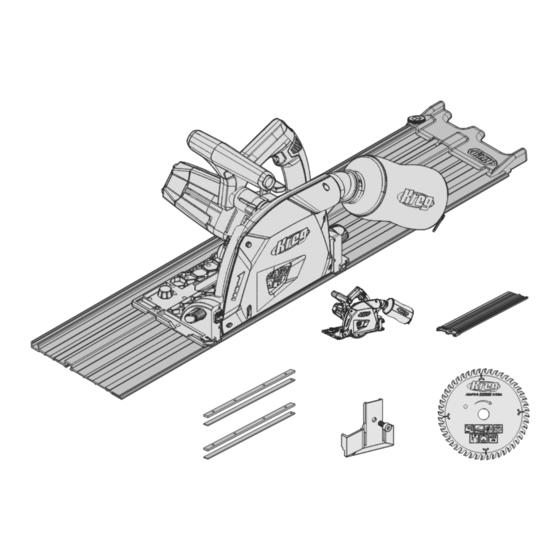
Guide Track Connectors
Items covered in this manual:
Plunge-Cut Track Saw
Saw Splinter Guard
Guide Tracks
Saw Blade
English
2
French
35
Spanish
69
Advertisement
Table of Contents


Need help?
Do you have a question about the ACS3100 and is the answer not in the manual?
Questions and answers