Advertisement
Quick Links
WARNING AND CAUTIONS:
•
TO AVOID FIRE, SHOCK, OR DEATH; TURN OFF POWER AT CIRCUIT BREAKER OR FUSE
AND TEST THAT POWER IS OFF BEFORE WIRING!
•
Risk of Electric Shock - Local codes may require more than one disconnect switch. De-
energize all disconnect switches before servicing the equipment.
•
Use this device with copper or copper clad wire only.
•
To be installed and/or used in accordance with appropriate electrical codes and regulations.
•
If you are unsure about any part of these instructions, consult an electrician.
SPECIFICATIONS
Dimensions : 13.3" x 11.3" x 7.7"
(338 x 287 x 196 mm)
Input Power : 110-277VAC, +/- 10%; 11W max; 6kV surge
protection
Operating Temperature : -40°C to +54°C
Radios : SNAP 2.4GHz 802.15.4; Wi-Fi 2.4Ghz 802.11 b/g/n;
Cellular 4G LTE
CAUTION
• The Central Base Station must be installed in accordance
with national, state, and local electrical codes and
requirements
• All work must be performed by qualified personnel
• Disconnect all power before installation or service
• Metal conduit and connector must be grounded
NEEDED MATERIALS
Mounting Hardware: Using hardware appropriate for the
installation and mounting surface (0.25" diameter screw or
bolt), use all six (6) 0.310" diameter mounting holes to mount
the unit
Screwdriver: A 1/8
Hex screwdriver or Allen key is required to
remove the wiring/bottom compartment cover
Needle-nose Pliers: For tightening antenna cable connections
if outdoor antenna kit is used
Conduit:
•
For indoor installations: 3/4" conduit fitting with a
cable strain relief or cable clamp is needed for indoor
installations. The power entry point is sized for a 3/4"
NPT (1.12" diameter).
•
For outdoor installations: A liquid rated (IP65/NEMA
4X) 3/4" conduit fitting is needed for outdoor
installations. The power entry point is sized for a 3/4"
NPT (1.12" diameter).
Note: To maintain IP rating of the unit, it must be installed
with a IP65/NEMA 4X fitting at the power and ethernet entry
points.
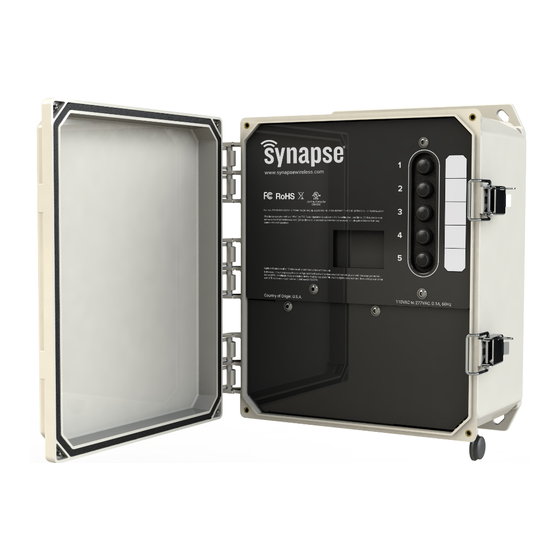
CBSSW-450-002 Central Base Station
Power Ratings: 110-277VAC; 11W max
Operating Temperature: -40 to +54 C
WARNINGS AND CAUTIONS:
•
Disconnect power at circuit breaker or fuse when servicing, installing, or removing fixture or
changing lamps.
•
Mounting: It is critical to the RF performance of this device that the enclosure be oriented
vertically. Enclosure must be mounted with door latch/lock on the right.
•
Metal conduit and connector must be grounded.
INSTALLATION GUIDE
WARNING: TO AVOID FIRE, SHOCK, OR DEATH: TURN
OFF POWER AT CIRCUIT BREAKER OR FUSE AND VERIFY
THAT POWER IS OFF BEFORE WIRING!
INSTALLATION INSTRUCTIONS
WARNING: DO NOT INSTALL THE CENTRAL BASE
STATION INSIDE A METAL ENCLOSURE. A metal
enclosure will obstruct the RF signals.
WARNING: DO NOT INSTALL THE CENTRAL BASE
STATION IN DIRECT SUNLIGHT. If installing the Central
Base Station outdoors, ensure that the Central Base Station is
provided some means of shading from direct sunlight. Installing
the unit in direct sunlight will substantially reduce maximum
operating temperature. Please install unit in shaded area or
provide a non-metallic sunshade that will not obstruct RF
signals.
1.
Select an installation location for the Central Base Station.
The best location provides direct line of sight between the
Central Base Station or the optional outdoor antenna and
at least two other lighting controllers in the network. The
antennas inside the Central Base Station rely on free
space around them for best RF performance so avoid an
installation near network cabling, AC power lines or metal
pipes.
2.
There are two ways to mount the Central Base Station
(CBS): using a pole strap (step 3) or screwing the CBS to
a wall with the screw holes (step 4).
WARNING: The CBS must be mounted vertically with
the conduit coming out of the bottom of the unit, or the
wireless signals may be compromised. DO NOT install
the CBS horizontally.
3.
You can mount the CBS to a pole using any Polycase pole
straps that are compatible with the Polycase©
enclosure.
4.
Using six (6) 0.25" diameter screws that can fit the 0.310"
diameter mounting holes and capable of supporting 50
lbs. of weight, screw the CBS to the wall.
5.
Remove the two screws and lower cover to access the
bottom
wiring compartment. (Figure 1). A flathead
screwdriver may be used to help lift and remove the
cover.
6.
Once the CBS is mounted and the wiring compartment
cover is removed, you must have a licensed electrician
connect
power into the CBS's wiring compartment
according the national, state, and local electrical codes
and requirements. The three connection points in the
wiring compartment are as
Black is Line
White is Neutral
Green is Ground
NOTE: To ensure safety and surge protection connect
the green ground wire to an earth ground.
7.
If you are using an outdoor antenna kit, please refer to
the "INSTRUCTIONS FOR INSTALLING OUTDOOR
ANTENNA KIT – OPTIONAL" section in this guide for the
necessary configuration steps.
8.
If you are not using an outdoor antenna kit, place the
lower cover back into position and tighten the two screws.
(Figure 1)
ZH-121006
Note: Door image removed for clarity.
NOTE: The Power entry cable is not provided. The power
entry hole is 3/4" knockout (1.12").
•
For indoor installations use a proper sized conduit
fitting with a cable strain relief or cable clamp.
follows:
Figure 1
DOC-1000598-B-4
Advertisement

Related Manuals for Synapse CBSSW-450-002


Summary of Contents for Synapse CBSSW-450-002
- Page 1 CBSSW-450-002 Central Base Station Power Ratings: 110-277VAC; 11W max Operating Temperature: -40 to +54 C WARNING AND CAUTIONS: WARNINGS AND CAUTIONS: • TO AVOID FIRE, SHOCK, OR DEATH; TURN OFF POWER AT CIRCUIT BREAKER OR FUSE • Disconnect power at circuit breaker or fuse when servicing, installing, or removing fixture or AND TEST THAT POWER IS OFF BEFORE WIRING! changing lamps.
- Page 2 ANTENNA KIT - OPTIONAL The Central Base Station includes an external connector on the bottom of the unit for use with the Synapse Outdoor Antenna CERTIFICATIONS Kit. This external antenna and cable help ensure that the...
Need help?
Do you have a question about the CBSSW-450-002 and is the answer not in the manual?
Questions and answers