
Related Manuals for Wadkin Bursgreen WB800H


Summary of Contents for Wadkin Bursgreen WB800H
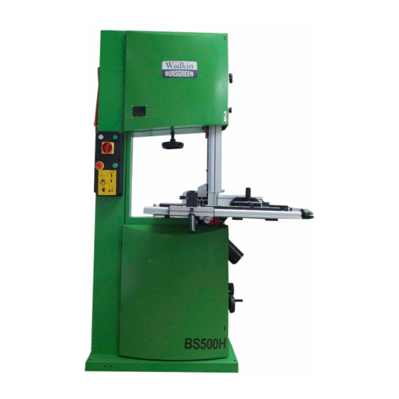
- Page 1 Wadkin Bursgreen WB800H Bandsaw Supplied by Advanced Machinery Services Tel: 0844 844 9949 Fax: 0844 844 4744 www.advancedmachinery.co.uk...
- Page 2 Wadkin Bursgreen WB Bandsaw Range...
-
Page 3: Specifications
CONTENT Specifications Fitting the Fence Rail General Safety Instructions Fitting the Rip Fence Special safety Instructions Set Up Blade safety Setting the Table Stop Use of Extension Leads Setting Up the Blade Tension & Tracking Safety Symbols Setting the Blade Guide Safety Symbols Used throughout this Manual Setting the Mobile Wheel Kit... -
Page 4: General Safety Instructions
advisable wherever possible to use an RCD GENERAL SAFETY INSTRUCTIONS (residual current device) at the mains socket. STAY ALERT: Always watch what you are doing Please read the following instructions carefully, and use common sense. Do not operate the saw failure to do so could lead to serious personal when you are tired or under the influence of injury. -
Page 5: Special Safety Instructions
DO NOT ABUSE THE MAINS LEAD: Never be carried out by qualified persons using original attempt to move the saw by means of the mains spare parts, otherwise this may result in lead or pull it to remove the plug from the mains considerable danger to the user. - Page 6 16. Before making the first cut using the saw, let it Always release the blade tension, when the run for a while; Watch for vibration or wobbling machine is not in use. that could indicate poor installation or a poorly balanced blade.
-
Page 7: Safety Symbols
SAFETY SYMBOLS Floor Load This machine represents a moderately large When using the saw always ensure the weight load in a small footprint. Most commercial operator as well as those in the area shop floors will be adequate for the weight of the wear ear protection. -
Page 8: Getting To Know Your Machine
GETTING TO KNOW YOUR MACHINE A. Lift Ring Fence Rail B. Switch Box J. Belt Tension Handwheel C. Blade Tension Handwheel K. Quick Release Lever D. Guide Post Handwheel L. Blade Tracking Lock knob & Star- E. Blade Guide & Guard Knob F. -
Page 9: Piece Inventory
UNPACKING Lifts out the bandsaw from crate with crane or forklift. The Heavy-Duty Bandsaw is shipped from the manufacturer in a carefully packed crate. If you discover the machine is damaged after you have signed for delivery, please call Customer Service Clean Up immediately for advice. -
Page 10: Fitting The Table
ASSEMBLY Fitting the table Fitting the guide post handwheel The table for this bandsaw is very heavy. Get help when placing it on the trunnion. Attach the guide post handwheel lever(B) to the guide post handwheel, tighten it with the 10mm With the help of another person, carefully lift the open wrench. -
Page 11: Fitting The Rip Fence
Fitting the fence rail SET UP To fit the fence rail, firstly check 4 winged screws Warning! Before carrying out any and washers(I) supplied into the 4 threaded holes maintenance or adjustments the on the bottom of the table. machine must be disconnected from the power supply. - Page 12 Setting up the blade tension & tracking Setting up the blade tension With the power supply disconnected, set the blade tension with the blade tension handwheel (N). Rotating the wheel in a clockwise direction will increase the blade tension and anti clockwise will decrease the tension.
- Page 13 Rotate the belt tension handwheel(V) to adjust the V-belt tension. Loosen the required allen bolt/s. Move the guide block, guide assembly and/or the Setting the Mobile Wheel Kit (optional) pole until the guide block is set in the correct position. Place “U”...
-
Page 14: Operation
OPERATION Switch Turn the POWER on or off using the Power Switch Turn the machine on using the green button on the switch box. Turn off the machine off using the red button, it also with the emergency-stop function, and they must be unlocked before turn the machine on. -
Page 15: Changing The Blade
Tilting the table to perform bevel cuts MAINTENANCE To use the table to perform a bevel cut, loosen the Changing the blade table trunnion locking lever(M) and turn the table tilt handle(Z) to tilt the table over to the desired angle. Warning! Unplug the machine from the Re-secure the locking lever(M). -
Page 16: Wiring Diagram
Cleaning: Caution! Before cleaning or carrying out maintenance work, disconnect the machine from the power source (wall socket). Never use water or other liquids to clean the machine. Use a brush. Regular maintenance of the machine will prevent unnecessary problems. Always remove excess chips and waste debris from the band-saw, pay particular attention around the motors air inlets, failure to do so... -
Page 17: Troubleshooting
TROUBLESHOOTING Warning: For your safety, always turn off and unplug the machine before carrying out any troubleshooting. Remedy Problem Possible Cause Check the cable for damage. The machine does not work Damaged mains lead. Check for power at the mains. when switched on: Problem with the electrical supply. -
Page 18: Parts List And Diagram
PARTS LIST & DIAGRAM Note: Always mention the model number in all correspondence regarding your bandsaw or when ording repair parts. Parts List (Diagram A) Description Description Allen screw M8x35 A-41 Hex nut M5 Cam shaft A-42 Hand wheel, belt tension Cam base A-43 Lever... - Page 19 Parts List (Diagram A cont. Description Description A-81 Block, pulley A-100 Scale, table tilt A-82 Motor pulley A-101 Table trunion, upper A-83 Set screw M8x10 A-102 Allen screw M8x30 A-84 Flat key A-103 Allen screw M10x20 A-85 Motor A-104 Ratchet lever, table tilt A-86 Hex nut M8 A-105 Block trunion...
- Page 20 Parts List (Diagram C) Description Description Taping screw ST4.2x10 C-23 Set screw M6x6 Cap , fence C-24 Handle, fine adjust Plate, fence C-25 Spring, gear Sunk head screw M4x10 C-26 Eccentric, fine adjust Fence C-27 Seat, fine adjust Wing nut M6 C-28 Rod, gear Guide plate, screw...
- Page 21 Parts List (Diagram E) Description Description Mitre gauge knob E-11 Mitre gauge rod Washer 6mm E-12 Pan head screw M4x18 Mitre gauge base E-13 Hex nut M4 Pan head screw M5x10 E-14 Scale, gauge Indicator gauge E-15 Taping Screw ST4.8x10 Block indicator E-16 End cap, Gauge fence...
- Page 23 DIAGRAM...
- Page 24 DIAGRAM...
- Page 26 DIAGRAM...
Need help?
Do you have a question about the WB800H and is the answer not in the manual?
Questions and answers