Table of Contents
Advertisement
Quick Links
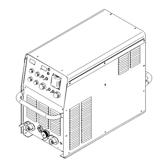
OPTIMARC CV/CC505
For use with machine Part Number K60169-1, Code 76452
Safety Depends on You
Lincoln arc welding and cutting
equipment is designed and built
with safety in mind. However, your
overall safety can be increased by
proper installation and thoughtful
operation on you part. DO NOT
INSTALL, OPERATE OR REPAIR
THIS EQUIPMENT WITHOUT
READING THIS MANUAL AND
THE SAFETY PRECAUTIONS
CONTAINED THROUGHOUT.
And, most importantly, think before
you act and be careful.
No. 195, Lane 5008, Hu Tai Rd. Baoshan, Shanghai, PRC 201907
• World's Leader in Welding and Cutting•
THE SHANGHAI LINCOLN ELECTRIC COMPANY
www.lincolnelectric.com.cn
Copyright © 2020 The Shanghai Lincoln Electric Company
IM7031-1
Feb, 2020
Rev. 01
Rev. 01
Advertisement
Table of Contents

Subscribe to Our Youtube Channel
Related Manuals for Lincoln Electric OPTIMARC CV/CC505


Summary of Contents for Lincoln Electric OPTIMARC CV/CC505
- Page 1 CONTAINED THROUGHOUT. And, most importantly, think before you act and be careful. Copyright © 2020 The Shanghai Lincoln Electric Company • World’s Leader in Welding and Cutting• THE SHANGHAI LINCOLN ELECTRIC COMPANY No. 195, Lane 5008, Hu Tai Rd. Baoshan, Shanghai, PRC 201907 www.lincolnelectric.com.cn...
- Page 2 Thank you for selecting QUALITY Lincoln Electric products. Please examine the packaging and equipment for damage. Claims for material damaged in shipment must be notified immediately to the authorized dealer from whom you purchased the machine. For future reference, please record your equipment identification information in the table below. Model Name, Code &...
- Page 3 SAFETY ® OPTIMARC CV/CC505 Rev. 01...
- Page 4 SAFETY ® OPTIMARC CV/CC505 Rev. 01...
- Page 5 SAFETY ® OPTIMARC CV/CC505 Rev. 01...
-
Page 6: Installation
For any maintenance or repair operation it is recommended to contact the nearest technical service center or directly consult machine division of the Shanghai Lincoln Electric. Maintenance or repairs performed by unauthorized service center or personnel will void the manufacturer’s warranty. -
Page 7: Safety Precautions
INSTALLATION SAFETY PRECAUTIONS Read the entire installation section before starting installation. INPUT POWER AND GROUNDING WARNING CONNECTION ELECTRIC SHOCK can kill. WARNING Only qualified personnel should perform this Only a qualified electrician should connect the installation. ® input leads to the OPTIMARC . - Page 8 INSTALLATION PROCESS SELECTIONS AND metal electrical contact. Poor work lead connections can result in poor welding performance. CONNECTIONS To avoid interference problems with other equipment and to achieve the best possible operation, route all WARNING cables directly to the work and wire feeder. Avoid excessive lengths and do not coil excess cable.
- Page 9 INSTALLATION LN-25 PRO FEEDER ( FIGURE A.3 ) Remote control methods Set the rotary switch to OPTIONAL (Default FCAW-S); Set the control switch to Feeder; The remote control box with order part numbers K60030-8M/-15M/-30M should be used to control the machine output and set the voltage, Use the wire feed speed pot on LN-25 to set the current.
- Page 10 INSTALLATION GTAW PROCESS ( CC MODE ) CONNECTION ( FIGURE A.4 ) Set the rotary switch to GTAW mode; Set the control switch to REMOTE The actual output current would be set by the remote device up to the maximum current set by local output pot. Recommended to use Foot Amptrol K870.
- Page 11 INSTALLATION 6-PIN AMPHENOL CONNECTOR INSTRUCTION CAUTION Please see FIGURE A.7 and TABLE A.3 for more For secure electrical connection, the screws details. connecting the output terminals and cables must be tightened. Damage may occur to the output stud or welding performance maybe compromised. 6-PIN LWF WIRE FEEDER CONNECTOR INSTRUCTION Please see FIGURE A.6 and TABLE A.2 for more...
- Page 12 INSTALLATION WARNING ELECTRIC SHOCK can kill. Do not touch electrically live parts or electrode with skin or wet clothing. Insulate yourself from work and ground. Always wear dry insulating gloves. FUMES AND GASES can be dangerous. Keep your head out of fumes. Use ventilation or exhaust to remove fumes from breathing zone.
-
Page 13: Operational Features And Controls
OPERATION OPERATIONAL FEATURES AND CV/CC505. CONTROLS 8. DIGITAL INDICATION VOLTAGE METER This meter displays the preset voltage before a weld FRONT PANEL (SEE FIGURE B.1) and the actual voltage during a weld . The actual voltage is displayed for 5 seconds after a weld ends. 1. - Page 14 OPERATION REAR PANEL (PLEASE SEE FIGURE B.2). 24. AUX. VOLTAGE RECEPTACLE Export type machine: This is a 220V 200W max. auxiliary power output socket, for plugging gas heater. 21. INPUT CABLE HOLDING BRACKET This bracket securely holds the three phase power cables in place.
- Page 15 OPERATION FIGURE B.3 FIGURE B.4 FIGURE B.5 ® OPTIMARC CV/CC505 Rev. 01...
- Page 16 OPERATION continue output at crater voltage and current to fill this crater. For more details, please see FIGURE B.5. DIP SWITCH DESCRIPTIONS 4. SPECIAL FUNCTION TEST ® OPTIMARC CV/CC machine offers a DIP switch on It enables a test procedure to test the control knobs the control board, which allows user to have additional and the toggle switches, when the DIP switch 4 is ON features.
-
Page 17: Troubleshooting
TROUBLESHOOTING If for any reason you do not understand the test procedures or are unable to perform the tests/repairs safely, contact your local authorized Lincoln Electric CAUTION Field Service Facility for technical assistance. Observe all Safety Guidelines detailed in the beginning and throughout this manual. - Page 18 TROUBLESHOOTING If for any reason you do not understand the test procedures or are unable to perform the tests/repairs safely, contact your local authorized Lincoln Electric CAUTION Field Service Facility for technical assistance. Observe all Safety Guidelines detailed in the beginning and throughout this manual.
- Page 19 Except for special instructions, experiments on welding machines are conducted in accordance with the general standard of IEC60974-1; experiments on welding consumables are conducted in accordance with the general standard of AWS; for speci c applicable standards on welding consumables please refer to the product page. The product performance data of this website and related attachments are from LINCOLN ELECTRIC American application engineering laboratory.
Need help?
Do you have a question about the OPTIMARC CV/CC505 and is the answer not in the manual?
Questions and answers