Table of Contents
Advertisement
Quick Links
Advertisement
Table of Contents

Related Manuals for Axis T99A12


Summary of Contents for Axis T99A12
- Page 1 AXIS T99A12 Positioning Unit 24 V AC/DC Installation guide...
-
Page 2: Table Of Contents
AXIS T99A12 Positioning Unit 24 V AC/DC Read this first .......... -
Page 3: Read This First
(STP) that is properly grounded. the patents listed at axis.com/patent and one or more Contact information additional patents or pending patent applications in Axis Communications Inc. -
Page 4: Contact Information
Class 1 electrical energy source (ES1) according 223 69 Lund to IEC/EN/UL 62368-1 Sweden We recommend the use of Axis power supply DIN PS24 480 W. Tel: +46 46 272 18 00 Fax: +46 46 13 61 30 When this product has reached the end of its useful life, dispose of it according to local laws and axis.com... -
Page 5: Safety Information
AXIS T99A12 Positioning Unit 24 V AC/DC Safety information Hazard levels DANGER Indicates a hazardous situation which, if not avoided, will result in death or serious injury. WARNING Indicates a hazardous situation which, if not avoided, could result in death or serious injury. - Page 6 • Use only spare parts provided by or recommended by Axis. • Do not attempt to repair the product yourself. Contact Axis support or your Axis reseller for service matters. • Use a yellow/green colored grounding cable of at least 0.5 mm or 20 AWG.
-
Page 7: Package Contents
AXIS T99A12 Positioning Unit 24 V AC/DC Package contents • Positioning unit • Power connector • I/O connector • Torx® bit T20 (long) and T30... -
Page 8: Product Overview
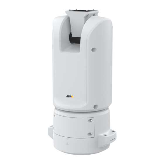
AXIS T99A12 Positioning Unit 24 V AC/DC Product overview Positioning unit (tilt) Positioning unit (pan) Base unit Camera (not included) - Page 9 AXIS T99A12 Positioning Unit 24 V AC/DC Illuminator cables (not to be used) Camera power cable Camera network cable Camera serial interface cable Input power connector I/O connector RJ45 connector SFP slot for SFP module (SFP module not included)
-
Page 10: How To Install The Product
AXIS T99A12 Positioning Unit 24 V AC/DC How to install the product DANGER Risk of electric shock. All cables shall be de-energized before installing the product. CAUTION The electrical connections and conduit installations shall be made by a certified electrician and in compliance with local regulations. - Page 11 AXIS T99A12 Positioning Unit 24 V AC/DC 3. Remove the base unit. NO TICE TICE TICE Do not use sharp tools when you remove the transparent base unit cover. 4. Remove the transparent base unit cover.
-
Page 12: Route The Cables
AXIS T99A12 Positioning Unit 24 V AC/DC Conduit cover clip Conduit cover Screw hole (x4) 5. For conduit installations only: remove the two conduit cover clips followed by the conduit cover. 6. Attach the base unit to the mounting surface with appropriate fasteners in the four screw holes. - Page 13 AXIS T99A12 Positioning Unit 24 V AC/DC Power cable (not included) Strain relief Grounding screw Grounding braid (not included) Bottom cable hole 1. Install the optional conduit adapters (not included). 2. Connect the grounding braid to the grounding screw. 3. Insert the power cable, I/O cable and network cable through the hole in the base unit as shown in the illustration above.
- Page 14 AXIS T99A12 Positioning Unit 24 V AC/DC I/O cable (optional, not included) Network cable (not included) 5. Insert the I/O cable (optional) through the strain relief with a distance of 420 mm (16.5 in) from the strain relief to the end of the cable.
- Page 15 AXIS T99A12 Positioning Unit 24 V AC/DC Power cable (not included) I/O cable (optional, not included) Network cable (not included) Cable gasket Transparent base unit cover 8. Fit cable gaskets on the cables. See Cable thickness on page 27. 9. Insert the power, I/O and network cables including the cable gaskets through the holes in the transparent base unit cover and arrange the cables as shown in the illustration above.
- Page 16 AXIS T99A12 Positioning Unit 24 V AC/DC 10. Place the transparent base unit cover on the base unit and fit the cable gaskets inside the holes. I/O connector Power connector O-ring NO TICE TICE TICE To not accidentally disconnect the unit from power if the cable is pulled, let the protective grounding wire be about 10 mm (0.4 in) longer than the other two wires (in the power...
- Page 17 AXIS T99A12 Positioning Unit 24 V AC/DC 13. Place the positioning unit on the base unit. Make sure that the arrows on the two units are aligned. 14. Turn the positioning unit clockwise back to its original position and tighten the four base unit screws (torque 3.0 Nm).
-
Page 18: Install The Network Link
For more information on network connector locations, see Product overview on page 8 . Note • SFP module is not included. For more information on available SFP modules, see axis.com • If you install a network link only via the optical fiber cable using the respective SFP module, it works as a stand-alone solution for long range cabling installations. - Page 19 AXIS T99A12 Positioning Unit 24 V AC/DC 1. Remove the cable gaskets from the camera’s bottom cover. 2. Insert the network/power/serial interface cable trough the holes in the bottom cover. 3. Fit the bottom cover on the positioning unit.
- Page 20 AXIS T99A12 Positioning Unit 24 V AC/DC 4. Tilt the bottom cover backward to its end position and tighten the two front screws of the positioning unit (T20, torque 3.0 Nm).
-
Page 21: Connect The Cables
AXIS T99A12 Positioning Unit 24 V AC/DC 5. Tilt the bottom cover forward to its end position and tighten the two rear screws of the positioning unit (T20, torque 3.0 Nm). 6. Connect the camera network, serial interface and power cables according to the camera’s installation guide. - Page 22 AXIS T99A12 Positioning Unit 24 V AC/DC Connect the cables 1. Loosen the four lid screws (T20) and remove the lid. Input power connector I/O connector RJ45 connector SFP slot for SFP module (SFP module not included) 2. Connect the network (optical fibre and/or RJ45), I/O and power cables. For more information on different network connectivity options, see Install the network link on page 17.
-
Page 23: Select The Ptz Driver
AXIS T99A12 Positioning Unit 24 V AC/DC Select the PTZ driver 1. Go to the camera’s webpage. 2. Go to System > Accessories > PTZ. 3. If your camera supports both PTZ drivers and digital PTZ, select PTZ mode Mechanical. -
Page 24: Specifications
AXIS T99A12 Positioning Unit 24 V AC/DC Specifications Connectors Network connector RJ45 Ethernet connector. SFP connector. NO TICE TICE TICE The product shall be connected using a shielded network cable (STP) or an optical fiber cable. All cables connecting the product to the network shall be intended for their specific use. - Page 25 AXIS T99A12 Positioning Unit 24 V AC/DC 3– Configurable Digital input – Connect to pin 1 to activate, or 0 to max 30 V DC (Input or leave floating (unconnected) to deactivate. Output) 0 to max 30 V DC, Digital output – Internally connected to pin 1 (DC...
- Page 26 AXIS T99A12 Positioning Unit 24 V AC/DC This table is only valid for the 24 V AC and the 24 V DC power connectors. Position 24 V AC 24 V DC Protective earth Protective earth + 24 V 24 V AC Phase...
-
Page 27: Cables
AXIS T99A12 Positioning Unit 24 V AC/DC RS485/RS422 TX A (TX) For full duplex RS485/RS422 RS485/RS422 TX B Cables Cable thickness The cable diameter, when using cable gaskets provided with the product, should be in the range of 5 to 11 mm (0.2 to 0.4 in). - Page 28 Installation guide Ver. M4.2 Date: September 2023 AXIS T99A12 Positioning Unit 24 V AC/DC © 2022 - 2023 Axis Communications AB Part no. 2734730...
Need help?
Do you have a question about the T99A12 and is the answer not in the manual?
Questions and answers