Table of Contents
Advertisement
Quick Links
Service Manual
This service information is designed for experienced repair technicians only and is not designed for use by the general public. It
does not contain warnings or cautions to advise non-technical individuals of potential dangers in attempting to service a product.
Products powered by electricity should be serviced or repaired only by experienced professional technicians. Any attempt to service
or repair the product or products dealt with in this service information by anyone else could result in serious injury or death.
All the components used in this equipment are important for safety. These parts are marked by a
Circuit Board Diagrams, Exploded Views and Replacement Parts List. It is essential that the parts should be replaced with
manufacturer's specified parts to prevent shock, fire or other hazards and lack of performance. Do not modify the original design
without permission of manufacturer.
TABLE OF CONTENTS
1. Safety Precautions --------------------------------------------------
2. Specifications ---------------------------------------------------------
2.1. Product Specifications ---------------------------------------
2.2. Name Plate -----------------------------------------------------
2.3. Dimensions -----------------------------------------------------
3. Location of Controls and Components ----------------------
4. Installation Instructions -------------------------------------------
4.1. Moving and Installing ----------------------------------------
4.2. Detergent Box Group ----------------------------------------
5. Operating Instructions ---------------------------------------------
5.1. LCD Screen, Function Buttons & Knobs ---------------
5.2. Program Details -----------------------------------------------
5.3. Child Lock ------------------------------------------------------ 10
6. Test Mode --------------------------------------------------------------
6.1. Autotest --------------------------------------------------------- 10
Drum Type Washing Machine
Model No.
Product Color
Destination
WARNING
IMPORTANT SAFETY NOTICE
2
3
3
3
4
5
6
6
7
8
8
9
10
1
NA-127VB6WAE/WAS/WPG
: White
: IRAN, OMAN, UAE
7. Service Mode -------------------------------------------------------------- 12
7.1. Service Autotest -------------------------------------------------
7.2. Failure Codes ----------------------------------------------------- 13
8. Troubleshooting Guide ------------------------------------------------ 13
9. Critical Torque Values -------------------------------------------------- 15
10. Disassembly and Assembly Instructions ---------------------- 16
11. Component Specifications ------------------------------------------ 26
11.1. Drain Pump ------------------------------------------------------ 26
11.2. Heater ------------------------------------------------------------- 27
11.3. NTC ---------------------------------------------------------------- 28
11.4. Valve --------------------------------------------------------------- 29
11.5. Electronic Pressure Switch (EPS) -------------------------- 30
11.6. Motor --------------------------------------------------------------- 31
11.7. Door Lock --------------------------------------------------------- 32
11.8. Circulation Pump--------------------------------------------
12. Wiring Diagram ---------------------------------------------------------
13. Exploded View and Spare Parts List ----------------------------- 36
© Panasonic Corporation 2015 Unauthorized copying
and distribution is violation of law.
Order No.
??
in the Schematic Diagrams,
12
33
34
Advertisement
Table of Contents

Related Manuals for Panasonic NA-127VB6WAE


Summary of Contents for Panasonic NA-127VB6WAE
-
Page 1: Table Of Contents
6. Test Mode -------------------------------------------------------------- 11.7. Door Lock --------------------------------------------------------- 32 6.1. Autotest --------------------------------------------------------- 10 11.8. Circulation Pump-------------------------------------------- 12. Wiring Diagram --------------------------------------------------------- 13. Exploded View and Spare Parts List ----------------------------- 36 © Panasonic Corporation 2015 Unauthorized copying and distribution is violation of law. -
Page 3: Specifications
2. Specifications 2.1. Product Specifications Model NA-127VB6 Product Type Front Loader Capacity 7 kg Max Spin Speed 1200 rpm Drum Volume 50 lt Energy Label Rating A+++ Energy Consumption 162 kWh / annum Water Consumption 9240 L / annum Wash 58 dBA Noise Level Spin... - Page 4 2.3. Dimension in millimetres NA-127VB6...
-
Page 5: Location Of Controls And Components
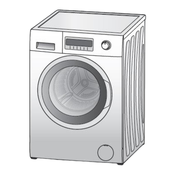
3. Location of Controls and Components... -
Page 6: Installation Instructions
4. Installation Instructions Moving and Installing 4.1. 4.1.1. Removal of Transportation Screw 4.1.2. Foot Adjustment 1. Transportation screws, which are located at the back side of 1. Do not install machine on rugs or similar surfaces. the machine, must be removed before running the machine. 2. -
Page 7: Detergent Box Group
4.1.4. Water Supply Connection 1. Washing machine is supplied with a single (cold) water inlet. 2. To prevent leakage from the connection joints, a rubber washer is included in the hose packing. Fit this washer at the end of water inlet hose on the tap side. 3. -
Page 8: Operating Instructions
5. Operating Instructions 5.1. LCD Screen, Function Buttons & Knobs Program selector 16 programs including off position Switch 1, Start / Pause Switch 2, Temperature Selection Switch 3, Spin Speed Selection Switch 4, Delay Timer Selection Switch 5, Extra Rinse Option Switch 6, Easy Ironing Option Switch 7, Eco/Speed Mode Option 7 Segment LCD for Temperature Display... -
Page 9: Program Details
5.2. Program Details... -
Page 10: Child Lock
5.3. Child Lock Activation The Child Lock Symbol on appears on the LCD display as Child Press SW7 for 5 seconds. Lock is active. Deactivation Press SW7 for 5 seconds. The Child Lock Symbol will disappear on LCD display upon deactivation. - Page 11 AUTOTEST Time in seconds (to be adjusted) Entering autotest Changing power to 220 50Hz Main Voltage 50 Hz Door Lock Powered (Depends on door lock) Motor Ramp to max spin (max. is 15 sec.) Time until motor is stopped (Depends on the motor stop time) Motor Preferred Run (Direction to Right) Motor Inverse Run (Direction to Left) EV1 (flowrate dependent of washer)
-
Page 12: Service Mode
7. Service Mode 7.1. Service Autotest 1. Set PR to program 3 (Colours) and press SW2 (T°C) 2. While pressing the SW2, change PR position from third to second, and release the SW2 button. program position) as soon as “SAU” is displayed on LCD. 3. -
Page 13: Failure Codes
7.2. Failure Codes Indication For User Indication For Service Error Indication Error Number Yes/No Yes/No Door is not locked Door is unlocked during programme Lack of water Pump failure Overflow NTC or Heater Failure Motor Failure - 1 (Tachometer open-short circuit or motor connector is disconnected) Motor Failure - 2 (triac short circuit) Electronic Pressure Sensor... -
Page 14: Critical Torque Values
FAILURE PROBABLE CAUSE METHODS OF ELIMINATION Press the start/pause button. In order to stop the foam, dilute one table-spoon of softener in Too much detergent has been half liter of water and pour it in the detergent Excessive foam in used. -
Page 15: Disassembly And Assembly Instructions
10. Disassembly and Assembly Instructions 10.1. Top Plate Remove two screws that fix the top-plate at the back Push the top-plate back and pull it up 10.2. Door Remove two screws that fix the door by using T25 tool Pull up the door Remove screws that fix the door group Put the door outside plastic with helping screwdriver Remove the door inside plastic... - Page 16 Remove the door handle Remove the door handle pin 10.3. Spring Wire First remove the spring wire fixing the tub bellows seal by using the small size screw driver. Pull the tub bellows Remove the tub bellows seal-body fixing spring seal 10.4.
- Page 17 Pull the control panel out 10.6. Electronic Card Release the socket fixing plastic by depressing the taps with Depress the taps fixing the card by using a screwdriver the help of a screwdriver Remove the card out off panel Remove the sockets on the card After releasing sockets, remove PCB box from its housing Disassemble the PCB box and its cover around the box...
- Page 18 Remove the LCD screen by depressing the taps by using a Remove the card from its housing and unplug its connector screwdriver 10.7. Front Panel Remove the screw fixing the front panel at the bottom Remove two screws fixing the door lock Remove the tub bellows seal Remove two screws fixing front panel to body Pull up front panel...
- Page 19 10.8. Support Bracket Remove two clips fixing detergent drawer housing to upper support bracket 10.9. Detergent Drawer Housing Remove the tub bellow hose by releasing the holder Unplug connectors from feed valve extensions of bellow hose Slightly turn the feed valve counter-clockwise to remove Remove the detergent drawer housing assembly 10.10.
- Page 20 Pull up the power cable group Remove EMI filter 10.11. Electronic Pressure Switch (EPS) Unplug EPS connector Pull up EPS 10.12. Door Lock Remove clamp from EPS hose Unplug door lock connector 10.13. Drain Pump Remove clamp holding drain hose by using a plier Remove clamp fixing tub outlet hose...
- Page 21 Unplug drain pump connector Remove screws holding drain pump 10.14. Front Counterweight Remove three screws on the front counterweight Gently pull out counterweight (Wrench size 13 mm) 10.15. Heater Unplug heater connectors Remove nut (8 mm) fixing the heater Pull out heater gently holding both sides...
- Page 22 10.16. Twinjet System Remove twinjet hoses from tub bellow seal pulling Remove screw fixing circulation pump them up Lay the appliance down and press on ratchet holding Remove circulation pump circulation pump Remove cable connector Remove hose connecting circulation pump to drain pump 10.17.
- Page 23 10.18. Transport Screw Remove four transport screws Hold the transport screw and pull it out 10.19. Upper Counterweight Remove two screws fixing the upper counterweight by Hold and carry out upper-counterweight using box wrench size 13 mm 10.20. Washing Group Unplug motor connectors Cut all the cable ties which fix cable group Remove the screws fixing hanger bracket...
- Page 24 10.21. Shock Absorber Pin 10.22. Driven Pulley Remove shock absorber pins squeezing the ratchet by a Remove the belt rotating the driven pulley pliers 10.23. Driven Pulley Remove the bolt at the center of pulley by tucking a Remove pulley wooden bar avoids rotation 10.24.
- Page 25 Remove tub outlet bellowed hose loosening screwed- Remove 19 screws around tub using box wrench size 8 mm clamp Remove drum Remove front tub...
-
Page 26: Component Specifications
Component Specifications 11.1. Drain Pump Drain pump is both mechanical and electrical component which is used to drain water inside the washing machine. It has a synchronous motor inside. For better performance maintenance, pump filter should be cleaned regularly. Drain pump Technical features Nominal voltage 220-240 V... -
Page 27: Heater
11.2. Heater Heating element (Resistance) is a component which is designed to regulate temperature of water inside the drum. It three connections: Phase, neutral ground connections. Resistance Technical features 2000 W (±5%) Heater type Tubular heating element Nominal power with NTC – sensor 26.4 ±5% Ω... -
Page 28: Ntc
11.3. NTC Component which sends signals to PCB about the water temperature inside the tub. The Resistance (Ohm) value of the NTC decreases as the temperature increases. Technical features R min R max R min R max (°C) (kΩ) (kΩ) (°C) (kΩ) (kΩ) -
Page 29: Valve
11.4. Valve Valve is an electrical and mechanical component which is designed to take water from the network system into the washing machine. It is operated by PCB card. Valve Technical features Nominal voltage 220-240 V 7 L/min (±15 %) Rated flow Nominal power 8 VA... -
Page 30: Electronic Pressure Switch (Eps)
11.5. Electronic Pressure Sensor (EPS) Electromagnetic field occurs due to movement of pressurized membrane. The spring moves vertically by nucleus due to electromagnetic field. The water level is regulated according to the frequency changes of the spring by electronic card. Testing component Push the door lock slider with screwdriver Select the 1st program and start the machine... -
Page 31: Motor
11.6. Motor The washing machine has an asynchronous motor. It is controlled by the PCB. It is essential to check the motor for correct diagnosis and quick servicing. In the below picture, socket points on the motor is shown to measure with multimeter. -
Page 32: Door Lock
11.7. Door Lock Door lock is activated at the beginning of the program in order to prevent the door from opening. Locking is generated by supplying power to PTC-bimetal, after max 6sec (220V), the bimetal will be warm and ready to close the contacts. Thus the first impulse to the solenoid will allow the contact to close and consequently the slider will be locked by the pin of the slider lock. -
Page 33: Circulation Pump
11.8. Circulation Pump The component is used for circulation of water inside the drum in order to increase washing performance. Circulation Pump Technical features Nominal voltage 220 - 240 V Frequency 50 Hz 169.5 Ω (±5%) Resistor (coil) Testing component Check the resistance value on the component with multimeter as shown below. -
Page 34: Wiring Diagram
Wiring Diagram (Board) - Page 35 12.1. Wiring Diagram (Socket)
-
Page 36: Exploded View And Spare Parts List
13. Exploded View and Spare Part List 13.1. Control Panel Spare Parts 13.1.1. Exploded View of Control Panel Parts (U): Indicates parts at the remarks that can be replaced by user. CP: Components identified with CP have special characteristics important for safety. When replacing any of these components use only manufacturer’s specified parts. - Page 37 13.1.2. Control Panel Spare Parts REF. NO PART NAME CODE MODEL REMARKS 42144365 NA-127VB6WAE DETERGENT DRAWER COVER 42144603 NA-127VB6WAS 42144377 NA-127VBWPG 42144364 NA-127VB6WAE CONTROL PANEL 42144602 NA-127VB6WAS 42144376 NA-127VB6WPG 20890092 NA-127VB6WAE ELECTRONIC CARD GR. 20608701 NA-127VB6WAS 20608701 NA-127VB6WPG PCB BOX...
- Page 38 13.2 Front Panel Spare Parts 13.2.1. Exploded View of Front Panel Spare Parts 13.2.2. Front Panel Spare Parts List REF. NO PART NAME CODE MODEL REMARKS BODY GROUP PAINTED 20813489 UPPER TRAY GROUP 42116356 FRONT PANEL GROUP 20827924 ADJUSTABLE FEET GR. 47000778 HOUSING FRAME BELLOW CLIP-PHYTON 37023407...
- Page 39 13.3 Washing Group Spare Parts 13.3.1. Exploded View of Washing Group Spare Parts...
- Page 40 13.3.2. Washing Group Spare Parts List REF. NO PART NAME CODE MODEL REMARKS REAR TUB GROUP 20790585 FRONT TUB 42059330 DRUM GROUP 20813458 MOTOR 32013066 TUB SEAL 42015077 DRIVEN PULLEY 37000499 BELT 42025178 COUNTERSUNK HEAD BOLT 8X28 TORX 37007899 TUB ENTERANCE WITH BELLOW HOSE 42087110 TUB BELLOWS SEAL 42025995...
- Page 41 13.3 Detergent Drawer Group Spare Parts 13.3.1. Exploded View of Detergent Drawer Group Spare Parts 13.3.2. Detergent Drawer Group Spare Parts List REF. NO PART NAME CODE MODEL REMARKS DETERGENT DRAWER 42065303 SIPHON COVER 42065308 DETERGENT DRAWER LOC. PART-BLUE 42065309 WATER DISTRIBUTION PLATE GR 42065322 DETERGENT DRAWER HOUSING...
- Page 42 13.5 Pressure Switch Hose Group Spare Parts 13.5.1. Exploded View of Pressure Switch Hose Group Spare Parts 13.5.2. Pressure Switch Hose Group Spare Parts List REF. NO PART NAME CODE MODEL REMARKS PRESSURE SWITCH HOSE (EPDM) 42078599 PRESSURE SWITCH WATER RESERVOIR 42088879 TUB EXIT BELLOWS GR(HOSE+BALL) 42127585...
- Page 43 13.6 Body Group Spare Parts 13.6.1. Exploded View of Body Group Spare Parts...
- Page 44 HANGER SPRING BRACKET PLS. 42016727 TUB HANGER SPRING PART (PLASTIC HOUSING 42019298 PART BETWEEN TUB AND SPRING HOOK) DRAIN HOSE HOLDING PLS 40014270 32017512 NA-127VB6WAE POWER CORD GROUP 32017511 NA-127VB6WAS 32017511 NA-127VB6WPG PRESSURE SWITCH MOUNTING CLIP 42022768 SPEED CONTROL HOLE STOPPER...
- Page 45 13.7 Porthole Group Spare Parts 13.7.1. Exploded View of Porthole Group Spare Parts 13.7.2. Porthole Group Spare Parts List REF. NO PART NAME CODE MODEL REMARKS OUTER DOOR PLASTIC 42093322 DOOR GLASS 47003771 INNER DOOR PLASTIC 42086999 HINGE II-M5 37015559 HINGE BUSHING II 42023907 DOOR HANDLE...
- Page 46 13.8. CIRCULATION GROUP 13.8.1. Exploded View of Circulation Pump Spare Parts 13.8.2. Circulation Pump Spare Parts List REF. NO PART NAME CODE MODEL REMARKS TUB BELLOWS SEAL 42025995 PUMP GROUP(FILTER)(THER. PROTECT.) 32006391 SCREW 4X14 PAN HEAD TYPE 2 37016360 ISO 7049 ST 4,2x13 TYPE 2 35008716 TWIN JET HORN/LEFT 42025993...
- Page 47 13.9. Accessories 13.9.1. Accessories...
- Page 48 13.9.2. Accessories Spare Parts List REF. NO PART NAME CODE MODEL REMARKS 52174913 ARABIC NA-127VB6WAE ENGLISH 52174912 52175338 ARABIC USER'S MANUAL NA-127VB6WAS 52175337 ENGLISH 52174926 ARABIC NA-127VB6WPG 52174925 ENGLISH 52174903 NA-127VB6WAE ENERGY LABEL 52175339 NA-127VB6WAS 52174931 NA-127VB6WPG LIQUID DETERGENT LEVEL PLATE...
- Page 49 13.10. Packaging Group Spare Parts 13.10.1. Exploded View of Packaging Group Spare Parts...
- Page 50 13.9.2. Package Group Spare Parts List REF. NO PART NAME CODE MODEL REMARKS BOTTOM STYROFOAM 52015437 TOP CARTON 52152496 REAR STYROFOAM(LEFT) 52027783 REAR STYROFOAM(RIGHT) 52027782 FRONT STYROFOAM LEFT 52027781 FRONT STYROFOAM RIGHT 52028076 CORNER CARDBOARD 47002042 TUB SUPPORT STYROFOAM 52005300 PACKAGE CARTON 52160507...
Need help?
Do you have a question about the NA-127VB6WAE and is the answer not in the manual?
Questions and answers