Table of Contents
Advertisement
Quick Links
5M78
DIN AC Strain Gage Conditioner
1
G
ENERAL
The Model 5M78 is a single-channel conditioner of phase-sensitive carrier-amplifier
design. Intended for applications involving transformer-coupling to the transducer
bridge (as with rotary-transformer torque sensors), this conditioner can also be used in
conventional installations when high sensitivity is required or where the electrical
environment is especially noisy. Responding only to the modulated carrier frequency,
the 5M78 rejects extraneous voltages that can cause errors in DC systems,
particularly when there is a need to "blow up" a portion of the transducer range.
User-adjustable phase and symmetry controls are provided.
The Model 5M78's is calibrated by means of a "two-point (dead-weight)" or
shunt-calibration technique, which are outlined in section three. The supplied shunt
calibration resistor is 59 kilohms, 1% which is located internally to the 5M78 case.
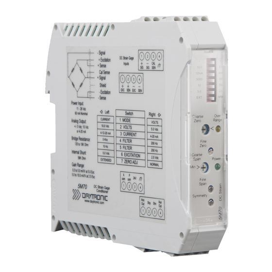
View of Side Label of the Model 5M78 AC Strain Gage Module
92342.00
AC Strain Gage
C
D
ESCRIPTION AND
G
ENERAL
M
ODEL
ONDITIONER
S
PECIFICATIONS
Model 5M78 AC Strain Gage Module
Access switch settings via the front
panel of the 5M78 by gently pulling the
clear plastic cover (from the bottom
side) so the cover rotates open from
the top. Use a small tool or finger to
place the switches to the left or right
position as you face the front of the
module. This process can be done with
or without power to the unit. Once
completed, return the cover to the
original position.
AC Strain Gage Phase Operation
Due to the AC modulated aspects of the
5M78 AC Voltage excitation circuit, the 5M78
contains a "PHASE" adjustment which
aligns the transducer's return output signal
to the conditioner's demodulator. When
the demodulator is aligned properly through
calibration, maximum amplitude and
accuracy are achieved.
D
S
ESCRIPTION AND
PECIFICATIONS
1.A.1.5M78
5M78
Module
5M78. 1
Advertisement
Table of Contents

Related Manuals for DayTronic 5M78

Summary of Contents for DayTronic 5M78
- Page 1 The Model 5M78's is calibrated by means of a “two-point (dead-weight)” or shunt-calibration technique, which are outlined in section three. The supplied shunt calibration resistor is 59 kilohms, 1% which is located internally to the 5M78 case. Model 5M78 AC Strain Gage Module...
- Page 2 WARNING Death, serious injury, or fire hazard could result from improper connection of this instrument. Read and understand this manual before connecting this instrument. Follow all installation and operating instructions while using this instrument. Connection of this instrument must be performed in compliance with the National Electrical Code (ANSI/NFPA 70-2014) of USA and any additional safety requirements applicable to your installation.
-
Page 3: Safety Precautions
WARNUNG Der falsche Anschluß dieses Gerätes kann Tod, schwere Verletzungen oder Feuer verursachen. Bevor Sie dieses Instrument anschließen, müssen Sie die Anleitung lesen und verstanden haben. Bei der Verwendung dieses Instruments müssen alle Installation- und Betriebsanweisungen beachtet werden. Der Anschluß dieses Instruments muß in Übereinstimmung mit den nationalen Bestimmungen für Elektrizität (ANSI/NFPA 70- 2014) der Vereinigten Staaten, sowie allen weiteren, in Ihrem Fall anwendbaren Sicherheitsbestimmungen, vorgenommen werden. -
Page 4: Medidas De Seguridad
Medidas de seguridad Las medidas de seguridad siguientes deberán observarse cuando se realice cualquier tipo de conexión al instrumento. ο Cuando se haga conexiones a circuitos eléctricos o a equipo de activación por pulso, deberá abrirse sus respectivas cajas de seguridad. NO deberá hacerse ninguna conexión del instrumento en líneas eléctricas bajo tensión. ο... -
Page 5: Standard Accessories
Sicherheitsvorkehrungen Die folgenden Sicherheitsvorkehrungen sind immer dann zu befolgen, wenn eine Verbindung zum Instrument hergestellt wird. ο Öffnen Sie beim Anschluß an elektrische Stromkreise oder Impulsauslösungseinrichtungen die entsprechenden Unterbrecher. Es dürfen KEINE Anschlüsse an das Instrument unter stromführenden Spannungsleitungen montiert werden. - Page 6 5M78 AC Strain Gage Module 5M78 S PECIFICATIONS Measurement Range: Adjustable 0.5 mV/V to 5.0 mV/V; nominal full-scale Transducer Types: Conventional 4-arm strain gage bridges, typically transformer coupled - 120 to 10 k ohm Excita tion: 3.28 kHz; Nominal 2.77 Vac rms, sensed Power Supply : 11 - 28 Vdc regulated;...
- Page 7 - wired as indicated (Fig. 1) Sense lines must be connected at the transducer (as recommended) or at the 5M78 screw terminals - as a minimum. Table 2 denotes screw terminal assignments...
- Page 8 3 GENERAL DESCRIPTION AND CALIBRATION The Model 5M78 is useful in applications involving tranformer coupling to the strain gage bridge (for example, rotary transformer torque sensors) and in certain appications that require high sensitivity with optimum signal-to-noise characteristics. Carrier amplifiers offer higher sensitivity than dc amplifiers and, since they respond only to the modulated carrier frequency, they reject certain extraneous voltages that can cause error in dc systems.
- Page 9 (see Figure 2). To perform calibration, proceed as follows. Turn power ON to the 5M78 DC Power input terminal (11 to 28 Vdc input) The front-panel indicator should light green to indicate the application of dc power.
- Page 10 Note: Above calculation is useful in applications involving non - star bridge shunt calibration strain gage bridges (for example DC bridges, and slip ring type torque sensors). Rotary transformer type sensors which use star bridge shunt circuit will not equate properly and the sensor's published calibration data should be referenced. Calibration 5M78.3...
- Page 11 Remote Cal function provides a convenient method of periodically monitoring calibration of the instrument in the positive or negative realm. Master/Slave Connections. When more than one 5M78 is being used in a measurement setup (instruments are closely mounted or the transducer cabling is in a common conduit or raceway), beat frequencies may be produced from the 3-kHz oscillators used in the instruments to develop the excitation.
-
Page 12: Verification Of Normal Operation
I/O connector using a short 4-wire cable configuration as shown in Figure 4. Attempt to balance the substitute simulated transducer. If conditions now appear to be normal, the transducer or cable is at fault. If the previous difficulties persist, the 5M78 is faulty. - Page 13 NOT PUSHED = Logic 1 (Shunt not enabled) PUSHED = Logic 0 (Shunt is enabled) Push Button (NO) 11 - 28 VDC POWER SUPPLY Contact Switch (NO) SHIELD Fig. 3 Shunt Connections Fig. 4 Star Bridge...
- Page 14 To prevent this, the user should declare one of the 5M78 units as a Master via switch 6 on the front panel. The other units should be switched to Slave and wired as shown with the SYC terminals connected and a separate Power Common wire.
-
Page 15: Product Warranty And Repair
AC Strain Gage Conditioner Module Product Warranty and Repair Daytronic Corporation warrants its products to be free from defects in material and workmanship, under normal and proper use in accordance with our instructions, for the period of time specified below. Our liability under such warranty or in... - Page 16 Daytronic Corporation Dayton OH w . . d d a a y y t t r r o o n n i i c c . . c c o o m...
Need help?
Do you have a question about the 5M78 and is the answer not in the manual?
Questions and answers