Table of Contents
Advertisement
Quick Links
Advertisement
Table of Contents

Related Manuals for Jouan SH 105


Summary of Contents for Jouan SH 105
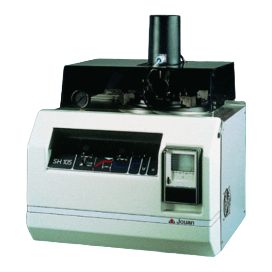
- Page 1 MEDIA PREPARATORS SH 105 /110 USER’S MANUAL 25529080-b...
- Page 2 25529080-b CAREFULLY READ THIS MANUAL BEFORE OPERATING YOUR INSTRUMENT. INFORMATION CONTAINED IN THIS DOCUMENT IS THE PROPERTY OF JOUAN ; IT MAY NOT BE DUPLICATED OR DISTRIBUTED WITHOUT THE OWNER’S AUTHORIZATION. THE VALIDITY OF THE GUARANTEE IS SUBJECT TO THE OBSERVATION OF THE INSTRUCTIONS...
- Page 3 REVISION STATUS INDEX DATE AMENDED PAGES NOTES 11/89 Initial release 01/90 5, 9, 12, 19, Fig. 3 Handle and F5 06/93 6.3, Figs. 4 & 5 Safety valve 08/02 Revised edition SH-U...
- Page 4 Other Countries : JOUAN S.A. : Service Assistance Technique 10, rue Duguay Trouin, 44807 SAINT HERBLAIN Cedex Tel. +33 (0) 2 28 03 20 00 - Fax. +33 (0) 2 28 03 20 01 - e-mail : jouan@jouan.com Website : www.jouan.com SH-U...
-
Page 5: Table Of Contents
CONTENTS CHAPTER 1 - USE AND FUNCTION ............1.1. -
Page 6: Chapter 1 - Use And Function
1 - 1 1 USE AND FUNCTION 1.1. OVERVIEW The SH105 and SH110 media preparators are automatic units for the preparation of culture media. They mix the constituents (water - dehydrated ingredients - additives . . .) and also sterilise and cool the me- dium according to data supplied by the operator. -
Page 7: Fluids
1 - 2 1.2. FLUIDS The fluids contained in the bowl must not be : - explosive, - comburants, - inflamable, - toxic. All the fluids used must belong to the group 2 of the European Pressure Directive 97/23 CE. Fluid used in the heating chamber (external circuit) = water (see Chapter 2.5). -
Page 8: Chapter 2 - Installation Procedure
2 INSTALLATION PROCEDURE 2.1. UNPACKING Check that the parts on the packing list are included in the package. If any parts are missing, contact your JOUAN agent. Remove all accessories and paperwork. 2.2. LIFTING AND TRANSPORT Due to the weight of the machine, all lifting and transporting must be carried out using proper handling equipment (eg : fork lift trolley) that complies with current regulations, and by people having undergone the necessary training. -
Page 9: Electrical Connection
2 - 2 2.5. ELECTRICAL CONNECTION Connect the supply cable to the mains. The electricity supply must be single-phase, 1 live, 1 neutral and 1 earth. The SH105 requires 10 A at 220 - 240 V A.C. (50 or 60 Hz depending on type). The SH110 requires more power : 13 A at 220 - 240 V. - Page 10 2 - 3 Water inlet tubing Water outlet tubing Pressure regulator Water level detector Steam condensor 2.6.1 WATER INLET The water supply pressure must be at least 2 bars. The water supply temperature must be between 10°C and 30°C if the unit is to work properly. The supply tube is connected to the lower port (point 1 and 3) with a hose coupling to ensure a water-tight connection.
-
Page 11: Weight And Dimensions
3 - 1 3 SPECIFICATIONS 3.1. WEIGHT AND DIMENSIONS SH105 SH110 Net weight (kg) Gross weight (kg) Width (mm) Depth (mm) Height : lid closed (mm) Height : lid open (mm) 3.2. MAINS ELECTRICITY 220-240 V / 50 Hz single-phase + earth 230 V / 60 Hz single-phase + earth 3.2.1 CONSUMPTION SH105... -
Page 12: Capacity By Volume Of Media
3 - 2 3.4. CAPACITY BY VOLUME OF MEDIA SH105 0.5 to 5 L. SH110 1.3 to 10 L. 3.5. MIXING SPEED 45 rpm 3.6. CHAMBER SPECIFICATION Stainless steel Chambers tested to 9 bars 3.7. TIMING OF STANDARD PROCESSING CYCLE SH105 SH110 Heating 20°... -
Page 13: Cycle Timing Control
3 - 3 3.9. CYCLE TIMING CONTROL By programmable timer adjustable by means of four buttons located under the display: FIG. 3.1 - TIMER The lower number indicates the setpoint time for sterilisation. The upper number indicates the time left for sterilisation. Do not use the “Valid”... -
Page 14: Description
4 - 1 4 INSTRUCTIONS FOR USE 4.1 DESCRIPTION 4.1.1 GENERAL VIEW The unit is mounted on a rigid chassis with painted sheet metal closed-in sides. FIG. 4.1 - GENERAL VIEW SH-U... - Page 15 4 - 2 Acrylic cover 13. Blood agar pushbutton Motor 14. Fast cooling pushbutton Motor and probe plug 15. On/off mains switch Locking system 16. Temperature recorder Sterilization indicator light 17. Heating jacket pressure gauge Dispensing indicator light 18. Control panel protective lid Temperature display 19.
- Page 16 4 - 3 4.1.3 REAR PANEL FIG. 4.3 - BACK OF SH 105 / SH 110 Mains cord Pressure regulator Mains fuse (Q = 1) Water level detector Electronique fuse Steam condensor Motor fuse Identification plate Water inlet tubing On/off mains isolation switch (CE model only)
- Page 17 4 - 4 4.1.4 TOP VIEW The top is made of stainless steel plate with : - Pressure gauge connected to the heating jacket to measure the pressure in the hydraulic circuit. - Acrylic safety cover fitted with a locking latch which, in the closed position, fits into the locking hole. - Heating jacket which holds the medium sterilisation chamber.
- Page 18 4 - 5 4.1.5 HYDRAULIC SYSTEM Safety valve (CE model only) FIG. 4.5 - HYDRAULIC CIRCUIT Heating chamber 15. Mixing paddle Preparation chamber 16. Heating chamber pressure gauge Heating element 17. Preparation chamber pressure gauge Water inlet tubing 18. Lid seal Pressure regulator 19.
-
Page 19: Setting Up
4 - 6 4.2. SETTING UP 4.2.1 SAFETY COVER The unit is fitted with an acrylic safety cover which is locked in the closed position when the unit is not switched on and the temperature of preparation chamber is above 65°C. Do not attempt to remove the cover when the unit is switched off. -
Page 20: Use
4 - 7 Important : - Remove the decompression valve head (point 21 figure 4.5) and fill with carded (sterile) cotton-wool to ensure filtering of bacteria during dispensing phase (see. Ch. 4.3, phase 6). The unit is now ready for use. 4.3. - Page 21 4 - 8 Phase 3 : Temperature build-up The temperature rises at 100°C/hour for the SH110, 135°C/hour for the SH105, which gives the following times for sterilising at 120°C with an initial water temperature of 20°C. - 1 hour for the SH110, - 45 minutes for the SH105.
-
Page 22: Voluntary Or Involuntary Interruption Of The Process
4 - 9 4.3.2 HEATING BLOOD-AGAR CYCLE Carry out phases 1 to 5 of the standard cycle. Phase 6 a : Adding blood at dispensing temperature. - Unscrew the additions port cap. Add the blood to the preparation chamber under sterile conditions. Replace the cap. -
Page 23: Maintenance After Use
4 - 10 4.4.3 AUTOMATIC DECOMPRESSION OF THE HEATING CHAMBER After use, opening the safety cover automatically engages the discharge electrovalve and decompresses the chamber. Then carefully follow the instructions in the “Maintenance after use” chapter. 4.5. MAINTENANCE AFTER USE 4.5.1 DECOMPRESSING THE MEDIUM CHAMBER Before removing the chamber lid, always : - Decompress the preparation chamber by screwing in the milled decompression knob. -
Page 24: Risks
Ensure that the unit is properly earthed when connected to the mains. 5.1.3 IN CASE OF CONTACT WITH FLAMES Have the instrument checked by the JOUAN Service Department or take it out of service. 5.1.4 MODIFICATION OF THE INSTRUMENT Any modification of the instrument is forbidden without the manufacturer's agreement. - Page 25 5 - 2 5.2.1 THERMAL PROTECTION The unit is fitted with two thermal cut-outs. - An electronic overheating sensor. If the temperature in the medium chamber exceeds 130°C, the heater is cut out and the cold water circulation system automatically cuts in. - A manually re-set safety thermostat mounted on the outside of the heating cuts out the heating circuit if the temperature is no longer controlled (breakdown in the electronic control system).
- Page 26 5 - 3 Locking system An automatically locking acrylic cover prevents access to the metal parts of the safety cover when the medium temperature is above 65°C. Switching off the unit also engages the locking system if the cover was in the "down" position. Unlocking : Normal procedure The cover is normally unlocked by a solenoid switch.
- Page 27 5 - 4 5.2.7 RELIEF VALVE In the event of abnormal overpressure in the medium chamber, the relief valve in the lid releases pressure above 2.2 bars. In such cases the safety cover protects the operators against scalding. 5.2.8 ON-LINE RELEASE VALVE This is incorporated in the hydraulic circuit and maintains the pressure in the heating chamber at 2.2 bars by releasing excess pressure by discharging water.
-
Page 28: Precautions
5 - 5 FIG. 5.4 - FUSE Mains cable Mains fuse (Q = 1) Electronic fuse (F2) Motor fuse (F3) 5.3. PRECAUTIONS 5.3.1 WATER CIRCUIT - Avoid introducing any foreign bodies into the heating chamber as this could damage the electro valves in the hydraulic circuit. - Page 29 5 - 6 5.3.2 CHAMBER LID See description in chapter 4.1.4 The chamber lid must be handled with care to avoid damaging the sensitive instruments such as : temperature probe, dispensing tube, mixing blade. Never lift the lid by the motor cover nor the temperature connecting lead. The decompression system must be filled with fresh carded cotton-wool every time the unit is used : - The chamber is decompressed by screwing the valve in.
-
Page 30: Cleaning
6 - 1 6 SERVICING AND PREVENTATIVE MAINTENANCE 6.1. CLEANING It is essentiel to clean the instrument after each use. 6.1.1 INTERNAL CHAMBER AND LID The underneath of the lid and the preparation chamber must be cleaned immediately after dispensing to prevent the agar gelling and sticking to parts of the unit. -
Page 31: Spare Parts List
6 - 2 Symptom Action Fluctuating dispense temp. Check water flow rate (2-3 litres per minute) . during start-up. Contaminated media. Check that carded cotton filter in decompression valve is clean. Check that the decompression valve screw is closed (UP) during the run.
Need help?
Do you have a question about the SH 105 and is the answer not in the manual?
Questions and answers