Table of Contents
Advertisement
Quick Links
Advertisement
Table of Contents

Related Manuals for Jouan C3i


Summary of Contents for Jouan C3i
- Page 1 CENTRIFUGE C3i / CR3i SERVICE MANUAL...
- Page 2 CENTRIFUGE C3i / CR3i SERVICE MANUAL 89000832-a CAREFULLY READ THIS MANUAL BEFORE OPERATING YOUR INSTRUMENT. INFORMATION CONTAINED IN THIS DOCUMENT IS THE PROPERTY OF JOUAN ; IT MAY NOT BE DUPLICATED OR DISTRIBUTED WITHOUT THE OWNER’S AUTHORIZATION.
- Page 3 REVISION STATUS INDEX DATE AMENDED PAGES NOTES 03/98 Initial release C3i-M...
- Page 4 (if any) recovered from such employee or agent and an amount equal to the legal costs (on a full indemnity basis) incurred by such employee or agent in defending or compromising the purchaser's claim). C3i-M...
-
Page 5: Table Of Contents
Unrefrigerated model (C3i) ........ - Page 6 Gas spring replacement on the C3i ........
-
Page 7: Chapter 1 - Introduction
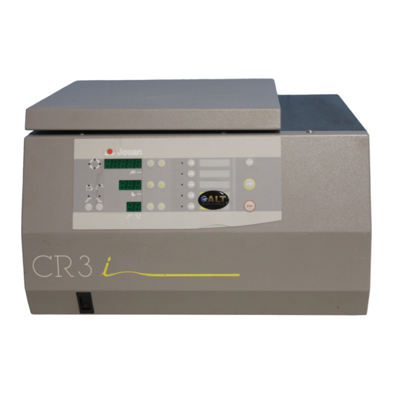
Tel. (540) 869 8623 - Fax : (540) 869 8626 - Toll free : (800) 662 7477 1.2. PRESENTATION The C3i and CR3i (refrigerated) centrifuges are instruments designed for laboratory use. Using relative centrifuge force (RCF) allows elements of different density to be separated. -
Page 8: Specifications
1.3. SPECIFICATIONS 1.3.1. DIMENSIONS AND WEIGHT Dimensions (H x W x D) C3i : 372 x 400 x 495 mm CR3i : 375 x 575 x 605 mm Packed (H x W x D) C3i : 600 x 610 x 540 mm... -
Page 9: Installation Procedure
IMPORTANT : at least two people are required to lift the centrifuge from the palette and place it on the bench. WARNING : The rear panel of the instrument must be at least 30 cm from the walls to allows hot air coming from the condenser to escape. C3i-M... -
Page 10: Chapter 2 - Theory Of Operation
2 - 1 2 THEORY OF OPERATION 2.1. DESCRIPTION The microprocessor system which controls the C3i or CR3i centrifuges ensures the operation of the following major elements : - Management of the operating modes - Generation of alternating current amplitude and frequency... - Page 11 2 - 2 CONTROL SYSTEM FLEXIBLE KEYBOARD AND DISPLAY LOCK ASSEMBLY USER SWITCH INTERFACE SWITCH TEMPERATURE (CR3i) SOLENOID TEMPERATURE BOWL (CR3i) MOTOR IMBALANCE COMPRESSOR (CR3i) SPEED POWER RACK AND FILTERS MOTOR SUPPLY FIG. 2.1 - CR3i FUNCTIONAL PRESENTATION C3i-M...
- Page 12 LID/BOWL SEAL MOTOR STABILIZER SUSPENSION IMBALANCE SENSOR GAS SPRING LID HINGE POWER INPUT RACK CENTRIGUGE BODY CENTRIFUGE BOWL LOCKING SYSTEM COMPRESSOR (CR3i) FRAME MOTOR FIXING BOLTS MICROPROCESSOR + POWER DISPLAY ASSEMBLY FRONT PANEL KEYBOARD FIG. 2.2 - CR3i EXPLODED VIEW C3i-M...
- Page 13 2 - 4 FIG. 2.3 - COMPONENTS OF THE C3i 1. Power supply rack 5. Lid lock solenoid 2. Imbalance sensor 6. Display assembly and keyboard 3. Induction motor 7. Microprocessor/power pcb 4. Centrifugation chamber bowl 8. Gas spring FIG. 2.4 - POWER SUPPLY RACK C3i 1.
- Page 14 6. Display assembly keyboard 3. Induction motor 7. Microprocessor/power pcb 4. Compressor 1. Mains socket 2. Compressor pcb 3. Braking resistances 4. Transformer 5. Ground/ earth 6. Motor earthing reactor 7. Mains filter 8. Rack FIG. 2.6 - POWER SUPPLY RACK CR3i C3i-M...
-
Page 15: Motor Control Principle
2.3. MOTOR CONTROL PRINCIPLE 2.3.1. INTRODUCTION The C3i / C R 3 i family of centrifuges is fitted with an asynchronous 3 phase motor. During the centrifugation, the microprocessor generates a system of sinusoidal 3 phase voltages, variable in amplitude and frequencies. During the braking phase the energy from the rotating parts is commuted across a resistance. -
Page 16: Power Control
The voltages applied to the motor phases are the compound voltages VR-VS, VS-VT,VT-VR and will vary between + E and - E ([O-(+E) = -E] Thus at the motor terminals are recreated the voltages whose amplitude is close to that of the mains. C3i-M... -
Page 17: Electronics - Structure
(fig. 2.3 or 2.5, item 7), whereas the second one is in the back of the front panel (fig. 2.3 or 2.5, item 6). The electronic imbalance sensor is located on the motor stabilizer (fig. 2.3 or 2.5, item 2) and allows the detection of and excessive imbalance due to the rotor loading. C3i-M... -
Page 18: Microprocessor + Power Pcb
The power supply for this zone is 12 VDC. The different signals coming to this zone are : - Bowl temperature. - Signal coming from the imbalance sensor - Tacho signal - Lid position signal - The motor overtemperature and the lid lock solenoid control. C3i-M... -
Page 19: Tacho Sensor
The tacho sensor is comprised of an optical sensor, which, generates two pulses per revolution. 2.4.5. TEMPERATURE SENSOR (CR3i) After the shaping circuit , the signal is 1.23 Vcc (0°C) ±80 mV/°C 2.4.6. REFRIGERATION CONTROL BOARD (CR3i) The board controls the power signal to the refrigeration group. C3i-M... -
Page 20: Input - Output
2 - 11 2.4.7. INPUT - OUTPUT +12 V GROUND/EARTH PROBE (°C) IMBALANCE (CR3i) OPTICAL TACHO MOTOR OVERTEMP + SOLENOID SWITCH 18 VAC INPUT SWITCHES SOLENOID COMMAND COOLING ON/OFF 230 VAC INPUT 300 VDC BUS MOTOR CONNECTION C3i-M... -
Page 21: Chapter 3 - Diagnostics And Repairs
3 DIAGNOSTICS AND REPAIRS 3.1. INTRODUCTION The C3i and CR3i are equipped with a diagnostic menu in order to help locate possible breakdowns. The possible conditions of incorrect functioning are communicated to the user by means of error codes on the display and buzzer alarms. - Page 22 Press simultaneously on the speed programming key and the PULSE key to allow complete resetting of the machine when it is next switched on. - Press START to pass to the next test - Press STOP to leave the test mode C3i-M...
- Page 23 Run cycles of the selected program can be run with a one minute pause between each. - - - Press to change the number of runs from 1 to 99. During a run, when rotating, displays are the same as they would be outside the test mode. C3i-M...
- Page 24 2 : total number of runs 3 : number of hours above 5000 rpm 4 : number of runs above 5000 rpm - Press START key to go back to test 1 - Press STOP key to exit from the test mode C3i-M...
-
Page 25: Fault Codes
Idem code 6 ERR 8 Motor overtemperature Idem code 6 (above 120°C) ERR 9 Chamber overtemperature Idem code 6 (above 50°C). ERR 10 Operating anomaly The machine is blocked and the keyboard is dead. Exit = Switch off the machine. C3i-M... -
Page 26: Troubleshooting Chart
No voltage being applied to the Check mains outlet and power cable. and no indicator centrifuge. lights ON. Fuses blown (C3i). Check for short circuits. Check the absence of short circuits with an ohm-meter (mains cable disconnected). Reset the circuit breaker (replace as required). - Page 27 Check by hand that the motor turns freely and without noise or abnormal friction. If necessary change the motor. 7) Starting impossible. µP board power bridge broken Change the µP board. All controls and down. display are Defective start switch. Change the keyboard. operational. C3i-M...
-
Page 28: Chapter 4 - Replacement Procedures
- To separate the stabilizer from the motor, insert Allen key n°4 between the cooling ribs of the motor perpendicularly to the screws. Repeat it for the 4 screws. Refitting - Carry out the above operations in the reverse order. FIG. 4.1 - DISMOUNTING THE MOTOR OF THE C3i C3i-M... -
Page 29: Refrigerated Model (Cr3I)
Screw in the bolts which will lift the stabilizer until it is rigidly mounted against the motor. FIG. 4.2 - DISMOUNTING THE MOTOR OF THE CR3i C3i-M... -
Page 30: Imbalance Detector Replacement
Dismounting - On the C3i, lift the bowl seal and remove the 3 press screws to remove the bowl. On the CR3i, remove the front panel by unscrewing the 5 screws and disconnecting the power switch, the flat cable, the display supply and the front panel ground cable. -
Page 31: Lid Lock Assembly Element Replacement
- Maintaining it, unscrew the screw located on the diagonal Refitting - Carry out the above operations in the reverse order. WARNING : THE MICROSWITCH ROD HAS TO BE SHAPED TO WORK PROPERLY AND TO GIVE A GOOD STROKE TO THE SOLENOID MOBILE CORE. C3i-M... -
Page 32: Solenoid Replacement
NB : Solenoid microswitch and lid lock microswitch replacement can be performed without having to remove the whole lid lock assembly. 4.5. POWER SUPPLY RACK REPLACEMENT 4.5.1. RACK REPLACEMENT FOR THE C3i Dismounting - Remove the front panel. - Unscrew the 2 screws at the back of the machine. -
Page 33: Rack Replacement For The Cr3I
This board is bound to the supply rack (figure 2.6, item 2). It will be necessary to remove the rack, as described below, to have access to the board. Dismounting - Disconnect the board. - Remove the board from the rack unscrewing the 4 screws (1). Refitting - Carry out the above operations in the reverse order. C3i-M... - Page 34 - Unscrew the 5 screws holding the board; one in each corner and one in the middle of the board. Remove the board. Refitting Carry out the above operations in the reverse order, and do not forget to place the insulation sheet between the board and its support. C3i-M...
- Page 35 4.8. GAS SPRING REPLACEMENT 4.8.1. GAS SPRING REPLACEMENT ON THE C3i The gas spring appears on the figure 2.3, item 8 (chapter 2). For its replacement follow the C3i motor replacement procedure (4.1.1). - Follow motor replacement procedure from step 1 to 4 (included).
- Page 36 - Remove the shock absorber by unscrewing the 3 fastening screws. - Unscrew the two locking screws of the optical sensor. Remove it while being careful of the cable. Refitting - Carry out the above operations in the reverse order. C3i-M...
- Page 37 - Open the lid. - As explained in the motor replacement procedure (4.1), extract the pin which binds the gas spring and the lid. - Unscrew the 5 screws which bind the lid to the hinge (1). - Remove the lid. C3i-M...
- Page 38 - Now, the centrifuge walls are separated from the body. To extract them, bend the wall to the outside (A) and lift the body (B). - The refrigeration group remains fixed only to the body. Refitting - Carry out the above opeartions in the reverse order. C3i-M...
- Page 39 If there is no conformity to condition 1, the motor can run erratically. If there is no conformity to condition 2, the motor can run irregularly with over heating. If there is no conformity to condition 3, the motor cannot run. C3i-M...
- Page 40 Referring to the following figure, it is very important to check : - The numbers and the correct positionning of washers. - The free movement along the centering core shaft. - The correct greasing of washer (see spare parts). C3i-M...
- Page 41 - Wait until the machine has completed the learning run. At the end of the run a value between 200 and 700 is displayed. If the result is different repeat the calibration. If you cannot succeed in having a good result, call the manufacturer’s service department. - Press STOP key to exit the configuration menu. C3i-M...
- Page 42 37, meaning that the calibration coefficient has been calculated with regard to a reference voltage corresponding to 37°C. - Press STOP key to exit from the configuration menu. - Put the J5 connector back in its former position. - Close the front panel. C3i-M...
- Page 43 6 - 1 6 SPARE PARTS - DIAGRAMS 6.1. GENERAL Item C3i Cat. N° CR3i Cat. N° Description 89000838 86001434 Power switch 85220838 85220761 Keyboard 89000840 89000840 Gas spring 89000839 89000839 Motor chamber/bowl seal 89000841 89000943 Lid/bowl seal 85280460 85280460 Main p.c.b.
- Page 44 6 - 2 6.2. MOTOR Item C3i Cat. N° CR3i Cat. N° Description 89000836 89000836 Motor 89000843 89000843 Load imbalance sensor 89000853 89000853 Elastic suspension 89000851 89000851 Spring washers 89000850 89000850 Washers 89000849 89000849 Motor shaft clamp 89000852 89000852 O-Ring...
- Page 45 6 - 3 6.3. AUTO-LOCK SYSTEM Item C3i Cat. N° CR3i Cat. N° Description 89002451 89002451 Guide collar 85230757 85230757 Latch 86001482 86001482 Spring 86001600 86001600 Circlip 89000917 89000917 Latch guide 89002391 89002391 Rotating equipment unlocking device C3i-M...
- Page 46 6 - 4 6.4. LOCK C3i lid lock CR3i lid lock Item C3i Cat. N° CR3i Cat. N° Description 89000842 89000842 Lid microswitch 89000844 89000844 Lock 89000845 89000845 Solenoid switch 89000846 89000846 Locking system spring 89000847 89000847 Lid solenoid 11202913...
- Page 47 6 - 5 6.5. FEEDER GROUP C3i feeder group CR3i feeder group Item C3i Cat. N° CR3i Cat. N° Description 89000900 89000900 Mains connector 85280383 Compressor p.c.b. 89000854 89000854 Braking resistor 89000837 89000837 Transformer 89000855 89000882 Feeder group C3i-M...
- Page 48 6 - 6 6.6. REFRIGERATION GROUP (CR3i) Item C3i Cat. N° CR3i Cat. N° Description 89000902 Bowl assembly 89000903 Condenser group assembly 230 V - 50 Hz 89000904 Condenser group assembly 120 V - 60 Hz 89000905 Compressor 230 V - 50 Hz...
- Page 49 6 - 7 6.7. CONDENSER GROUP (CR3i) Item C3i Cat. N° CR3i Cat. N° Description 89000907 Condenser 89000908 Screw 89000909 Fan blades 89000910 Motor nuts 89000911 Carter fan blades and motor 89000912 Motor 230 V - 50 Hz 89000913 Motor 120 V - 60 Hz...
- Page 50 0 - 500 V - ampmeter 0 - 10 A - ohmmeter 0 - 1 MΩ - frequency-meter 0 - 2 KHz Thermo-electric couple thermometer or similar with an accuracy of ± 1°C in the range 0 - 40°C C3i-M...
- Page 51 Rack wiring diagram 120 V (refrigerated version) ..........C3i-M...
Need help?
Do you have a question about the C3i and is the answer not in the manual?
Questions and answers