
Related Manuals for vissonic VIS-UHD0808-VW


Summary of Contents for vissonic VIS-UHD0808-VW
- Page 1 VIS-UHD0808-VW 8x8 Seamless 4K Ultra HD Matrix and Video Wall Processor User Manual V1.0 VISSONIC ELECTRONICS LIMITED...
- Page 2 The meaning of symbols ■ Safety instructions For your safe and correct use of equipments, we use a lot of symbols on the equipments and in the manuals, demonstrating the risk of body hurt or possible damage to property for the user or others.
- Page 3 Important note Warning In order to ensure the reliable performance of the equipment and the safety of the user, please observe the following matters during the process of installation, use and maintenance: The matters needing attention of installation Please do not use this product in the following places: the place of dust, soot and electric conductivity dust, corrosive gas, combustible gas;...
- Page 4 Matters needing attention in discarding product Electrolytic explosion: the burning of electrolytic capacitor on circuit boards may lead to explosion; Please collect and process according to the classification, do not put into life garbage; Please process it as industrial waste, or according to the local environmental protection...
- Page 5 Preface This manual mainly describes the use, performance parameters and troubleshooting of VISSONIC VIS-UHD0808-VW 8x8 seamless 4K Ultra HD matrix and video wall processor. . If the technical parameters and system usage in this manual are changed, the manufacturer will update the version of the manual.
-
Page 6: Table Of Contents
Context 1. Overview ............................7 1.1 Features ..........................7 1.2 Installation ........................... 8 2. Hardware description ........................9 3. Description of the front and rear panels ..................10 4. Network protocol ........................11 5. PC software introduction......................14 5.1 Connection ........................14 5.2 Login .......................... -
Page 7: Overview
1. Overview VIS-UHD0808-VW is a professional seamless UHD video matrix switching and splicing wall processor with HDMI 8 in 8 out. It provides ultra-high data transfer rates, and perfectly supports synchronous seamless switching of HDMI signals, resolutions up to 4K@60, 4:4:4, creative video wall layouts through an intuitive Web GUI, and FPGA-based pure hardware architecture can be extensive. -
Page 8: Installation
13) Input marker - a marker is added to each input signal to distinguish between different inputs. 14) Captions - You can add scrolling captions or welcome signs to the wall. 15) Input test images - An input can automatically generate test images for engineering debugging and test purposes. -
Page 9: Hardware Description
2. Hardware description Product parameters: Model VIS-UHD0808-VW Input type 8xHDMI,8xIR,8x analog audio Output type 8xHDMI,8x IR,8x analog audio Protocol HDMI 2.0, HDCP 2.2 Resolution, Up to 4096 x 2160@60Hz (4:4:4) HDMI port Type A, 19 pin, female Serial interface... -
Page 10: Description Of The Front And Rear Panels
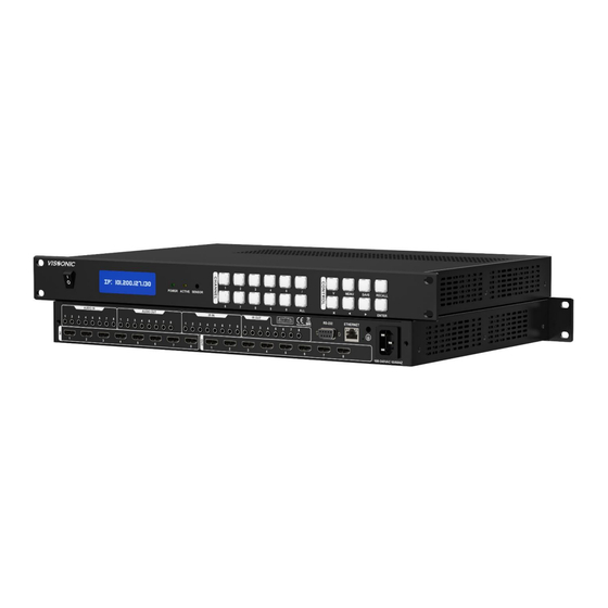
3. Description of the front and rear panels Figure 1 VIS-UHD 0808-VW front panel and rear panel The front and rear panels of the VIS-UHD 0808-VW seamless UHD Matrix switcher include: 1. Power switch - Power on or off the matrix switcher. -
Page 11: Network Protocol
4. Network protocol Protocol: TCP, IP: 192.168.1.188, port: 80 Protocol table: Order Function description Parameter description Return information {“type” : ”UHD0808”,“ MCU” : ”Ver1.2/Ver1.1/ Ver1.3”,“FPGA”:”Ver1 {param=version} Version query .2/Ver1.1/Ver1.3/Ver1.2” {“video1”:X1, Mode: Y 0: Single “video2”:X2, screen mode,1: One “video3”:X3, row and two columns 2: “video4”:X4,... - Page 12 ,”subnet”:”A”,”mac”:”B” network parameters {param=&ip,ip=%d.%d .%d.%d,gateway=%d.% Settings->Set network d.%d.%d,subnet=%d.% parameters d.%d.%d,mac=%x:%x: %x:%x:%x:%x}, {param=XVIDEOY} Video source switching X:input,Y:output X:input audio (1-8) No {param=XAUDIOY} Audio switching X: input infrared (1-8) No {param=XIRY} Infrared switch X : Splicing rows and {param=modeX} Splicing settings columns (0--6)...
- Page 13 Volume 0--100 {param=MuteOn[x]} Output mute on x: Output channel {param=MuteOff[x]} Output mute off x: Output channel Output channel y:1920x1080x60Hz!/38 {param:Port[x]/[y]} Set output resolution 40x2160x60Hz! Resolution list reference UHD_HDMI : {param output audio x: Output channel y: 0: Analog_sel[x]/[y]} selection number 1:Simulation...
-
Page 14: Pc Software Introduction
5. PC software introduction 5.1 Connection 1. The router is connected to the CAT5 network cable for TCP/IP communication. The default IP address of the matrix is 192.168.1.188. The IP addresses assigned by routers must be on the same network segment. -
Page 15: Matrix Switching Page
Check whether the device IP address and port number are correct, and then enter the password of the default account. IP address: 192.168.1.188, port number: 804. Login and password is ADMIN and admin123 5.3 Matrix switching page ① Video: Click here to switch to the Matrix switch page. - Page 16 ① Rename: Can change the input signal name. ② Graphic testing: Input can automatically generate test images for engineering debugging and testing. ③ Marker setting: A marker can be added to each input signal to distinguish between different inputs.
- Page 17 ④ EDID: Click on "EDID" and open an "EDID" control window. Select an input in the signal list and click "EDID" "Read Output to Input" Select the output you want to read and click "Apply" "Update EDID" Click "Browse", select the EDID file to be updated to open, and click "Upload".
- Page 18 ⑥ Resolution: View the input resolution. The right click function of the output port is shown as follows: ① Rename: You can change the output port name. ② Resolution: Output resolution to view or change. Support resolution: 800x600x60Hz 1024x768x60Hz...
-
Page 19: Fast Splicing Control
14) 1920x540x50Hz 15) 1920x540x50Hz 16) 1920x540x60Hz 17) 1920x1080x30Hz 18) 1920x1080x50Hz 19) 1920x1080x60Hz 20) 1920x1200x60Hz 21) 3840x2160x30Hz 22) 4086x2160x30Hz 23) 3840x2160x60Hz 24) 4086x2160x60Hz ③ Graphic test: Output test images to test whether the output port and display device are properly connected. -
Page 20: Audio Switching Matrix
③ Mode: Splicing mode, supports up to 7 splice wall modes. Supports single screen, left-right 1x1, up-down 1x1, 2x2, 2x3, 3x2, 4x2. Splicing modes correspond to ports: Single screen has no splicing, each output port outputs independently. -
Page 21: Infrared Switching Matrix
Right-click functions for audio output ports include renaming and clearing. 5.6 Infrared Switching Matrix Allows for freely switching infrared channel control. -
Page 22: Setting
5.7 Setting ① Network Settings: View connected device network IPs, change network settings, restore factory settings, etc. ② Other Settings: Logout, subtitle settings for the splice wall, language switch between Chinese and English, user management, software auto-login settings, and device buzzer toggle. -
Page 23: About
U (Underline): Underline the subtitle font. Upload Characters: Upload the configured characters to the current splice wall. Note: Set the characters before uploading. For example, if bold is not set before uploading, clicking bold after uploading will have no effect. So, configure before uploading, or else you'll need to upload new subtitles. - Page 24 www.vissonic.com...
-
Page 25: Web Control
6. Web control 6.1 Connection Can be connected to the router via CTA5 Ethernet cable for TCP/IP communication. The matrix's default IP address is 192.168.1.188. Please configure the connected router to be in the same network segment. If controlling from the PC, please set the following IP. -
Page 26: Matrix Switching Control
6.2 Matrix Switching Control ① Video: Click to quickly switch to the matrix control interface. ② Input Signal List: Check for input signals here. A green status indicates signal input, while default black signifies no signal input. Right-click functions in the signal list include graphic testing, logo settings, EDID, volume adjustment, and resolution settings. -
Page 27: Fast Splicing Control
6.3 Fast splicing control ① Splice: Click to quickly switch to the splice control interface. ② Splice Wall: Displays the current mode and signals for the splice wall; signals can be dragged to splice. ③ Mode: Splicing mode, supports up to 7 splice wall modes. -
Page 28: Audio Switching Matrix
6.4 Audio switching matrix ① Audio: Quick switch to audio control. ② Audio Output Ports: Displays and allows switching of audio signals for current output ports. Supports independent switching between analog and digital audio, with audio matrix capability. 6.5 Infrared switching matrix ①... -
Page 29: Setting
6.6 Setting ① Setting: Quickly switch to the settings menu. ② Matrix Network Settings: Displays the current network IP address of the connected matrix. Allows modification of the network IP address and factory reset. 6.7 Version ① About: Quickly switch to the version viewing interface. -
Page 30: Front Panel Button Operations Guide
7. Front Panel Button Operations Guide 7.1 Matrix switching Example 1: To switch the matrix from "Input 1" to "Output 2", follow these button operations: Press sequentially. Display Screen Printing Comments Select "Input 1" Press once for the matrix switch symbol "V."... - Page 31 Press sequentially. Display Screen Printing Comments IP SETTING Display IP Address 192.168.001.188 Enter modification; the cursor for editing will appear Move the cursor to the desired modification position. Input the desired modification value ENTER Set Succeed! Setting Successful Modify the port number, gateway, and subnet mask using the same steps as before. Press "IP" to enter the relevant interface, then navigate and modify as needed.
-
Page 32: Common Faults And Solutions
8. Common Faults and Solutions Symptoms of Malfunctions Solutions Check command accuracy Matrix Unable to Switch If there's no response, verify the device wiring. Ensure the device is receiving proper power. Verify the proper functioning of the device's respective ports and firmware version through command transmission or PC web inspection.
Need help?
Do you have a question about the VIS-UHD0808-VW and is the answer not in the manual?
Questions and answers