Table of Contents
Advertisement
Available languages
Available languages
Quick Links
Advertisement
Table of Contents

Subscribe to Our Youtube Channel
Related Manuals for Imi Heimeier UH8-RF V2

Summary of Contents for Imi Heimeier UH8-RF V2
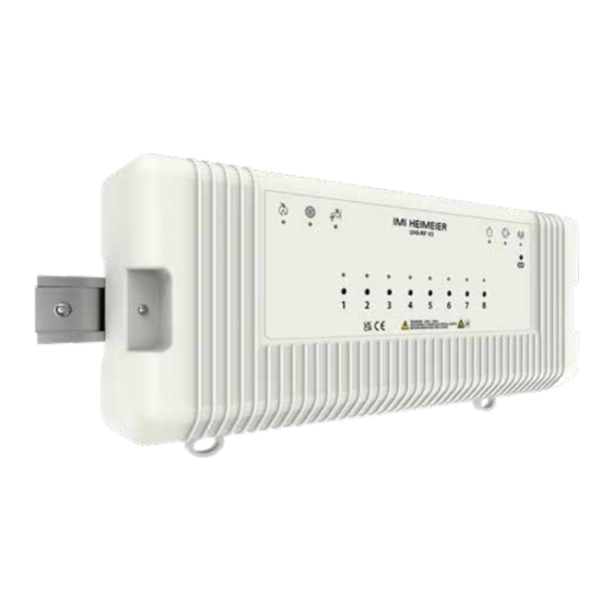
- Page 1 UH8-RF V2...
-
Page 3: Table Of Contents
Installation ....................25 Câblage UH8-RF V2 ...................26 Schéma de câblage – UH8-RF V2 Raccordement direct de la pompe ..28 Schéma de câblage – UH8-RF V2 avec UFH et vanne de radiateur ....30 Configuration des réglages .................32 Configuration du circuit ................33 Notes/Notizen/Notes ..................34... -
Page 4: Uh8-Rf V2 - Installation Manual
UH8-RF V2 – Installation manual Description Other functions The UH8-RF V2 is an 8 Zone central wiring centre for use with Creepage IMI Heimeier RF thermostats. During hot weather the heating is not normally needed as often, this means that valves and pumps that are not being used can seize and The UH8-RF V2 can be used to control any actuator or valve, which refuse to operate. -
Page 5: Installation
When DIN Rail mounting, you first need to insert the two clips provided on the back of the UH8-RF V2, as shown in the image; • On the back of the UH8-RF V2, position the clip in the middle and slide down. -
Page 6: Uh8-Rf V2 Wiring
UH8-RF V2 wiring The UH8-RF V2 should be fitted as close as possible to the equipment it is controlling, but never within a metal enclosure, if this cannot be avoided an extension antenna (EA1) must be fitted and placed outside the metal enclosure. - Page 7 Each Zone has an indicator light and button associated with it. cooling is in demand. Light functions: When activated, the sensor sends a signal back to the UH8-RF V2, 1. Light on when the zone output is on. and will shutdown cooling to the manifold. During this time, the dew 2.
-
Page 8: Wiring Diagram - Uh8-Rf V2 Direct Pump Connection
Wiring diagram – UH8-RF V2 Direct pump connection Select Zone Switch Position to match your system Wiring key ENABLE CREEPAGE 1. Radiator with Zone Valve end switch HEAT ENABLE 1 2. Radiator with Actuators - enables heat output DELAY (MINS) 2 3. - Page 9 Front panel connection CONNECTOR Recommended cable for Dew point sensor: 2 3 4 5 6 7 8 9 101112 Multi-core screened. Dew point sensor ZONE 6 ZONE 7 ZONE 8 1 2 3 1 2 3 1 2 3 ZONE 6 ZONE 7 HOT WATER HEAT...
-
Page 10: Wiring Diagram - Uh8-Rf V2 With Ufh And Radiator Valves
Wiring diagram – UH8-RF V2 with UFH and Radiator valves Select Zone Switch Position to match your system ENABLE CREEPAGE 1. Radiator with Zone Valve end switch HEAT ENABLE 1 Wiring key 2. Radiator with Actuators - enables heat output DELAY (MINS) 2 3. - Page 11 Front panel connection CONNECTOR Recommended cable for Dew point sensor: 2 3 4 5 6 7 8 9 101112 Multi-core screened. Dew point sensor ZONE 6 ZONE 7 ZONE 8 1 2 3 1 2 3 1 2 3 ZONE 6 ZONE 7 ZONE 8 HOT WATER...
-
Page 12: System Setup
1 2 3 4. Heat Enable Delay 2 minutes. When a thermostat is in demand, the UH8-RF V2 will activate the Zone output to actuators only, PUMP and In normal use these DIP switches can be ignored and should be left HEAT outputs will remain off. -
Page 13: System Configuration
System configuration PLEASE COMPLETE DURING INSTALLATION UH8-RF V2 Title:....................In use Zone type Zone title Underfloor Radiator Zone 1 Zone 2 Zone 3 Zone 4 Zone 5 Zone 6 Zone 7 Zone 8 Hot water... -
Page 14: Uh8-Rf V2 - Installationsanleitung
UH8-RF V2 – Installationsanleitung Beschreibung Weitere Funktionen Die UH8-RF V2 ist eine 8-Zonen-Klemmleiste für die Verwendung mit Pumpenschutzfunktion den IMI Heimeier RF-Thermostaten. Diese Funktion hilft zu vermeiden, dass sich Pumpen oder Ventile durch die geringe Nutzung, außerhalb der Heizsaison zusetzen und UH8-RF kann zur Ansteuerung aller 230-V AC Stellantriebe oder beschädigt werden. -
Page 15: Installation
Clips auf der Rückseite der UH8-RF V2 einsetzen, wie in der Abbildung gezeigt; • Positionieren Sie den Clip auf der Rückseite der UH8-RF V2 in der Mitte und schieben Sie ihn nach unten. • Die Punkte A und B werden in die entsprechenden Löcher gesteckt und eingerastet. -
Page 16: Anschlussdiagramm Uh8-Rf V2
Anschlussdiagramm UH8-RF V2 Die UH8-RF V2 sollte so nah wie möglich an dem zu steuernden Gerät angebracht werden, jedoch niemals innerhalb eines Metallgehäuses. Wenn dies nicht vermieden werden kann, muss eine Verlängerungsantenne (EA1) angebracht und außerhalb des Metallgehäuses platziert werden. - Page 17 Taupunktsensor (nur Kühlbetrieb) Tasten und Anzeigen in den Zonen 1 bis 8 Die Taupunktüberwachung hilft, das Risiko von Kondensation Jede Zone verfügt über eine Kontrollleuchte und eine Taste, die ihr während des Kühlbetriebs zu verringern. zugeordnet ist. Wenn der Sensor aktiviert wird, sendet er ein Signal an die UH8-RF LED-Funktionen: V2 und schaltet die Kühlung des Verteilers ab.
-
Page 18: Anschlussdiagramm - Uh8-Rf V2 Direkter Pumpenanschluss
Anschlussdiagramm – UH8-RF V2 Direkter Pumpenanschluss Select Zone Switch Position to match your system Legende ENABLE CREEPAGE 1. Radiator with Zone Valve end switch HEAT ENABLE 1 2. Radiator with Actuators - enables heat output DELAY (MINS) 3. UFH enables zone, manifold pump and heat output... - Page 19 Anschlussplatine Stecker (für Abdeckhaube) Empfohlenes Kabel für Taupunktsensor: 2 3 4 5 6 7 8 9 101112 Mehradrig abgeschirmt. Taupunktsensor ZONE 6 ZONE 7 ZONE 8 1 2 3 1 2 3 1 2 3 ZONE 6 ZONE 7 ZONE 8 Warmwasser- Heizen Taupunktsensor-...
-
Page 20: Anschlussdiagramm - Uh8-Rf V2 Mit Fbh Und Heizkörperventile
Anschlussdiagramm – UH8-RF V2 mit FBH und Heizkörperventile Select Zone Switch Position to match your system ENABLE CREEPAGE 1. Radiator with Zone Valve end switch HEAT ENABLE 1 Legende 2. Radiator with Actuators - enables heat output DELAY (MINS) 2 3. - Page 21 Anschlussplatine Stecker (für Abdeckhaube) Empfohlenes Kabel für Taupunktsensor: 2 3 4 5 6 7 8 9 101112 Mehradrig abgeschirmt. Taupunktsensor ZONE 6 ZONE 7 ZONE 8 1 2 3 1 2 3 1 2 3 ZONE 6 ZONE 7 ZONE 8 Warmwasser- Heizen Taupunktsensor-...
-
Page 22: System Einrichten
3. Heizverzögerung 1 Minute. Wenn ein Thermostat angesteuert wird, aktiviert die 1 2 3 4. Heizverzögerung 2 Minuten. UH8-RF V2 nur den Zonenausgang zu den Stellantrieben, die Ausgänge PUMP (Pumpe) und HEAT (Heizen) bleiben Bei normalem Gebrauch können diese DIP-Schalter ignoriert werden ausgeschaltet. -
Page 23: Konfiguration Des Systems
Konfiguration des Systems BITTE BEI DER INSTALLATION AUSFÜLLEN UH8-RF V2 Title:....................Aktiv Art der Zone Titel der Zone Fußboden- Heizkörper heizung Zone 1 Zone 2 Zone 3 Zone 4 Zone 5 Zone 6 Zone 7 Zone 8 Warmwasser... -
Page 24: Uh8-Rf V2 - Manuel D'installation
Si un signal est reçu d’une horloge d’eau chaude sanitaire sur le circuit, seule la sortie H/W sera active. Il s’agit d’une sortie L’UH8-RF V2 est une centrale de contrôle pour 8 zones à utiliser avec temporisée, qui alimente normalement le thermostat du ballon les thermostats IMI Heimeier RF. -
Page 25: Installation
• Placez l’UH8-RF V2 sur le rail DIN par le haut. • Tirez le clip vers le bas et poussez le bas de l’UH8-RF V2 sur le rail DIN. • En relâchant le clip, l’UH8-RF V2 est verrouillé en place sur le rail DIN. -
Page 26: Câblage Uh8-Rf V2
Câblage UH8-RF V2 L’UH8-RF V2 doit être installé aussi près que possible de l’équipement qu’il contrôle, mais jamais à l’intérieur d’un boîtier métallique. Si cela ne peut pas être évité, une antenne déportée (EA1) doit être installée et placée à l’extérieur du boîtier métallique. - Page 27 Fonctions d’éclairage : Lorsqu’il est activé, le capteur envoie un signal à l’UH8-RF V2 et 1. S’allume lorsque la sortie de zone est activée. arrête le refroidissement du collecteur. Pendant ce temps, le voyant 2.
-
Page 28: Schéma De Câblage - Uh8-Rf V2 Raccordement Direct De La Pompe
Schéma de câblage – UH8-RF V2 Raccordement direct de la pompe Select Zone Switch Position to match your system Indications de câblage ENABLE CREEPAGE 1. Radiator with Zone Valve end switch HEAT ENABLE 1 2. Radiator with Actuators - enables heat output DELAY (MINS) 2 3. - Page 29 Connexion sur le panneau avant Connecteur Câble recommandé pour le capteur de point de rosée : Câble multiconducteur blindé 2 3 4 5 6 7 8 9 101112 Capteur de point de rosée ZONE 6 ZONE 7 ZONE 8 1 2 3 1 2 3 1 2 3 ZONE 6...
-
Page 30: Schéma De Câblage - Uh8-Rf V2 Avec Ufh Et Vanne De Radiateur
Schéma de câblage – UH8-RF V2 avec UFH et vanne de radiateur Select Zone Switch Position to match your system ENABLE CREEPAGE 1. Radiator with Zone Valve end switch HEAT ENABLE 1 Indications de câblage 2. Radiator with Actuators - enables heat output DELAY (MINS) 2 3. - Page 31 Connexion sur le panneau avant Connecteur Câble recommandé pour le capteur de point de rosée : Câble multiconducteur blindé 2 3 4 5 6 7 8 9 101112 Capteur de point de rosée ZONE 6 ZONE 7 ZONE 8 1 2 3 1 2 3 1 2 3 ZONE 6...
-
Page 32: Configuration Des Réglages
Position 1 - Sortie de zone uniquement 1 2 3 4. Délai d’activation du chauffage 2 minutes Lorsqu’un thermostat est en demande, l’UH8-RF V2 active la sortie Zone vers les moteurs uniquement, les sorties Dans le cadre d’une utilisation normale, ces commutateurs DIP PUMP et HEAT restent désactivées. -
Page 33: Configuration Du Circuit
Configuration du circuit À COMPLÉTER LORS DE L’INSTALLATION UH8-RF V2 titre : ....................En cours Type de zone Nom de la zone d’utilisation Plancher Radiateur chauffant Zone 1 Zone 2 Zone 3 Zone 4 Zone 5 Zone 6 Zone 7... -
Page 34: Notes/Notizen/Notes
Notes/Notizen/Notes... - Page 36 Consultez les spécifications techniques directement sur notre site web : www.imi-hydronic.com Products commonly used with the UH8-RF V2 wiring centre Produkte, die üblicherweise mit der UH8-RF V2 Klemmleiste verwendet werden Produits couramment utilisés avec la centrale de contrôle UH8-RF V2...
Need help?
Do you have a question about the UH8-RF V2 and is the answer not in the manual?
Questions and answers