Table of Contents
Advertisement
Quick Links
Advertisement
Table of Contents

Related Manuals for gunt ET 796

Summary of Contents for gunt ET 796
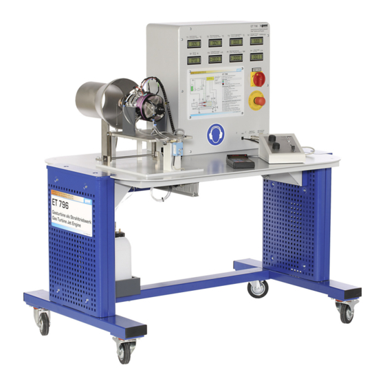
- Page 1 Instruction Manual ET 796 Gas Turbine as Jet Engine...
- Page 3 DTP_3 11/2007 ET 796 GAS TURBINE AS JET ENGINE Instruction Manual Please read and follow the safety regulations before the first installation! Publication-no.: 916.000 00 B 796 03 (A) DTP_3...
-
Page 4: Table Of Contents
11/2007 GAS TURBINE AS JET ENGINE ET 796 Table of Contents Introduction ........1 System description . - Page 5 11/2007 GAS TURBINE AS JET ENGINE ET 796 The open gas turbine process......37 4.1 Representation in heat diagram ......38 4.1.1...
-
Page 7: Introduction
11/2007 GAS TURBINE AS JET ENGINE ET 796 Introduction With the ET796 experimental module the function and performance of a gas turbine can be demon- strated and studied on model scale. Gas turbine systems are used to generate mechanical and electrical energy: •... - Page 8 11/2007 GAS TURBINE AS JET ENGINE ET 796 The experimental module includes a one-shaft system. All components necessary for the operation of the system are combined in a compact arrangement on a trolley on castors. The system is of straightforward construction and is specially designed for training purposes.
-
Page 9: System Description
11/2007 GAS TURBINE AS JET ENGINE ET 796 System description The experimental module includes a complete gas turbine system with the following subsystems: – Model gas jet turbine comprising com- pressor (1), turbine (2), combustion chamber (3) and thrust nozzle with thrust gauge (4). - Page 10 11/2007 GAS TURBINE AS JET ENGINE ET 796 Fig. 2.1 Prozessdiagram Gasturbine 2 System description...
-
Page 11: Function
11/2007 GAS TURBINE AS JET ENGINE ET 796 Function 2.1.1 Jet turbine The core of the plant is the model jet turbine Fig. 2.2 Model jet turbine It consists of an axial turbine with a direct coupled radial compressor and an annular combustion chamber. - Page 12 11/2007 GAS TURBINE AS JET ENGINE ET 796 tube by way of bores(6) in order to cool the very hot combustion gases (approx. 2000°C) down to the permissible turbine inlet temperature of 600 - 800°C. A glow plug (7) ignites the air/fuel mixture during starting.
- Page 13 11/2007 GAS TURBINE AS JET ENGINE ET 796 The bearings are cooled by the compressor air and The electronics (13) for the starter motor (15), tem- perature monitoring and speed measurement (14) are located under the front hood. The exhaust gas jet draws additional secondary air through the thrust tube by injection.
-
Page 14: Fuel System
11/2007 GAS TURBINE AS JET ENGINE ET 796 2.1.2 Fuel system Kerosene or petroleum is used as the fuel. To lubricate the turbine bearings a little oil is added to the fuel (ratio: 1:20). The turbine has a vacuum system with an evaporator. An electric fuel pump delivers the fuel to the turbine's evaporator tubes. -
Page 15: Controls
11/2007 GAS TURBINE AS JET ENGINE ET 796 Controls All the indicators, the master switch and the emergency-off switch are located on the front panel. 1 Compressor temperature T ET 796 2 Combustion chamber temperature T 3 Turbine output temperature T... - Page 16 11/2007 GAS TURBINE AS JET ENGINE ET 796 The turbine is operated from a control panel positioned in front of the turbine. It contains the status displays of the control electronics (1) as well as a port for the turbine's display and programming unit GSU (2).
-
Page 17: Layout Of The Experimental Module
11/2007 GAS TURBINE AS JET ENGINE ET 796 Layout of the experimental module All the system parts are set up on a benchtop frame. Only the fuel tank and the holder for the disposable gas cylinder with EN417 connector are located underneath the bench. -
Page 18: Setting Up And Maintaining The Gas Turbine
11/2007 GAS TURBINE AS JET ENGINE ET 796 Setting up and maintaining the gas turbine 2.4.1 Checking the gas turbine Before the gas turbine is run for the first time, it must be checked for damage in transit and maladjustment. -
Page 19: Setting Up
11/2007 GAS TURBINE AS JET ENGINE ET 796 2.4.2 Setting up Owing to the large amount of fresh air it requires (approx. 500 m /h), the gas turbine must only be operated in large, well ventilated premises. There should be a facility to discharge the exhaust gases directly to the outside, or to connect an exhaust pipe. - Page 20 11/2007 GAS TURBINE AS JET ENGINE ET 796 – Secure the assembly against rolling by actuating the castor brakes. – To ensure maintenance and service accessi- bility, there should be a clearance of at least 1 metre around the experimental module.
-
Page 21: Operation Of The Gas Turbine
11/2007 GAS TURBINE AS JET ENGINE ET 796 Operation of the gas turbine 2.5.1 Preparations for starting Before starting the gas turbine, the following tasks are to be carried out: – Check the fuel tank level. If fuel is topped up, the corresponding amount of lubricating oil must be added. - Page 22 11/2007 GAS TURBINE AS JET ENGINE ET 796 – Venting is carried out in test mode using the "Jet-tronic" control unit of the turbine pro- vided for connection at the control panel (see JetCat instructions). Release fuel hoses: Hold down the blue ring on the hose cou- plings and pull on hose.
-
Page 23: Starting Up The Gas Turbine
11/2007 GAS TURBINE AS JET ENGINE ET 796 2.5.2 Starting up the gas turbine The gas turbine is started by following a set procedure. This is typical for all gas turbines. Differences only arise due to variations in the degree of automation. In the following sketch the procedure is shown schematically over time. - Page 24 11/2007 GAS TURBINE AS JET ENGINE ET 796 It is advisable to carefully read through and digest the description of the starting procedure before performing the experiment. It is advisable to monitor the speed and tempera- ture curves on the turbine's GSU display and programming unit (see instructions to JetCat turbine).
-
Page 25: Operation Of The Gas Turbine
11/2007 GAS TURBINE AS JET ENGINE ET 796 Automatic starting process for gas turbine – The starter motor brings the turbine up to starting speed (yellow LED lit). – The glow plug is activated and auxiliary fuel is given to the glow plug. The tur- bine ignites. -
Page 26: Shutting Down The Gas Turbine
11/2007 GAS TURBINE AS JET ENGINE ET 796 2.5.4 Shutting down the gas turbine The gas turbine is shut down by way of the gas turbine's mode switch (AuxChan). – Regular shutdown by setting auto off. The turbine speed is set for a short time to 50000 - 60000 rpm. -
Page 27: Maintenance
11/2007 GAS TURBINE AS JET ENGINE ET 796 Maintenance 2.6.1 Glow plug In case of starting problems, check the glow plug for damage or dirt clogging. Glow plug burn-out is indicated by the control electronics. – Hold rubber jack and pull lightly on the cable to retract the spring in the jack and then de- tach the jack from the glow plug. -
Page 28: Faults And Fault Rectification
11/2007 GAS TURBINE AS JET ENGINE ET 796 Faults and fault rectification This section deals with any problems occurring in the system, and their causes. Turbine-specific faults and the meanings of the fault messages are detailed in the turbine manufacturers' instructions. - Page 29 11/2007 GAS TURBINE AS JET ENGINE ET 796 DANGER! After an aborted start there may still be unburned fuel in the turbine. The fuel may combust in an uncontrolled manner on restart and result in destruction of the turbine by overheating.
-
Page 30: Software
11/2007 GAS TURBINE AS JET ENGINE ET 796 Software The software should be installed in line with the separate installation instructions. After starting the program, the language must be selected once. The program has four tasks: – Clear display of important variables –... - Page 31 11/2007 GAS TURBINE AS JET ENGINE ET 796 Left-hand side of new window: - time interval - number of measured values Right-hand side: - switch on left: attach measuring points to existing data set on right: attach data set to...
- Page 32 GAS TURBINE AS JET ENGINE ET 796 – system diagram This view shows the current measured values in a clear process diagram. – About GUNT Shows information about GUNT. – EXIT Exits the program. Fig. 2.16 System diagram • File –...
- Page 33 11/2007 GAS TURBINE AS JET ENGINE ET 796 – new curve (only with “measurement diagram”) Creates a new data set. – load curve (only with “measurement diagram”) Loads a saved data set. – save curve (only with “measurement diagram”) Saves a data set.
- Page 34 11/2007 GAS TURBINE AS JET ENGINE ET 796 • Edit (only with “measurement diagram”) – take measuring point The current measured value is added to the measured value list, the data set. – delete measuring point The selected measuring point is deleted from the measured value list.
- Page 35 11/2007 GAS TURBINE AS JET ENGINE ET 796 • Language – Deutsch – English – Francais – Espanol Create a data set and plot first measured value: -Start- -chart- -File- -new- -name & path- -ok- Measured points are plotted in the graph using the buttons.
-
Page 37: Safety Instructions
11/2007 GAS TURBINE AS JET ENGINE ET 796 Safety instructions It is imperative that the following instructions are observed for the hazard-free and safe operation of the unit. All persons involved in the use of this unit, particularly students, are to be made aware of these safety instructions. -
Page 38: Hazards For Life And Limb
11/2007 GAS TURBINE AS JET ENGINE ET 796 Hazards for life and limb DANGER OF ELECTRIC SHOCK! Caution, high voltage. – Prior to opening the switch cupboard, unplug from the mains. – Work on the electrical system is only to be performed by suitably qualified personnel. -
Page 39: Special Safety Rules For Handling Kerosene
11/2007 GAS TURBINE AS JET ENGINE ET 796 HAZARD AREA! It must always be ensured that when the turbine is running, no-one is at the run level of the turbine. Staff should either position themselves in front of or behind the turbine, and not to the side. -
Page 40: Hazards For Unit And Function
11/2007 GAS TURBINE AS JET ENGINE ET 796 Hazards for unit and function DANGER OF FIRE! Do not bring flammable materials into contact with the hot exhaust gas pipe or place them in the exhaust jet. Flammable or heat-sensitive materials must be kept well away from the outlet area. - Page 41 11/2007 GAS TURBINE AS JET ENGINE ET 796 ATTENTION! The turbine must not draw in any foreign bodies or dust. Dust will deposit in the turbine bearings and destroy them. The intake area and the interior of the hood must be kept free of loose objects.
-
Page 43: The Open Gas Turbine Process
11/2007 GAS TURBINE AS JET ENGINE ET 796 The open gas turbine process The gas turbine demonstration stand operates according to the open circuit process, in which Fuel the working medium is taken from the environment and returned to it. -
Page 44: Representation In Heat Diagram
11/2007 GAS TURBINE AS JET ENGINE ET 796 Representation in heat diagram Representation in a heat diagram, a so-called T/s diagram, is suitable for assessment of the conditions in the circuit process. In it, the tempera- ture of the working medium is plotted over the specific entropy. -
Page 45: Thermal Efficiency (Ideal)
11/2007 GAS TURBINE AS JET ENGINE ET 796 4.1.1 Thermal efficiency (ideal) The efficiency is produced from the ratio between the input heat and the mechanical work. Assuming a constant heat capacity of the working medium, the resultant thermal efficiency is: With a mean value of k = 1.4 for air and 2-atomic... -
Page 46: Specific Work Capacity
11/2007 GAS TURBINE AS JET ENGINE ET 796 4.1.2 Specific work capacity The following correlation applies to the specific work capacity: æ ö × × ÷ - × × 0 285 ç 0 285 è ø It can be seen that, as well as the compression ratio, the intake and turbine inlet temperatures are of relevance. -
Page 47: Representation In P/V Diagram
11/2007 GAS TURBINE AS JET ENGINE ET 796 4.1.3 Representation in p/v diagram The circuit process can also be represented in a p/v diagram. This demonstrates the compression and expansion process particularly clearly. Heat input q Expansion Useful work Compression Heat output q Fig. -
Page 48: Gas Turbine As Jet Engine
11/2007 GAS TURBINE AS JET ENGINE ET 796 Gas turbine as jet engine In aircraft engines, above a certain air speed it is more favourable to utilise the exhaust gas jet directly to generate thrust. The simplest jet engine comprises of a single-shaft gas turbine (1) in an open process. -
Page 49: Experiments
11/2007 GAS TURBINE AS JET ENGINE ET 796 Experiments Recording of measurements The measurements should only be taken with the turbine in a steady state. The following measure- ments are exemplary and subject to substantial spread, dependent on various factors including ambient conditions. -
Page 50: Air Mass Flow And Fuel Mass Flow
11/2007 GAS TURBINE AS JET ENGINE ET 796 Air mass flow and fuel mass flow The air mass flow & m in kg/s is calculated as follows: × é ù é ù & × × Display ë ê û ú... -
Page 51: Further Characteristic Quantities Of An Aeroplane Jet Turbine
11/2007 GAS TURBINE AS JET ENGINE ET 796 Further characteristic quantities of an aeroplane jet turbine Calculations based on full load. specific thrust mit & & & & » & × =145 0 4 . specific fuel consumption & ×... - Page 52 11/2007 GAS TURBINE AS JET ENGINE ET 796 thermal efficiency (ideal) mit k = 14 . 0 285 with p: ratio of compression p = with p pressure before compression pressure after compression 0 189 0 285 2 09 internal efficiency or efficiency(real) useful power &...
- Page 53 11/2007 GAS TURBINE AS JET ENGINE ET 796 external efficiency or propulsive efficiency (real) thrust power useful power with P : thrust power × = Air speed; standing=0) overall efficiency × 5 Experiments...
-
Page 54: Evaluation Of Measurement Results
11/2007 GAS TURBINE AS JET ENGINE ET 796 Evaluation of measurement results 5.4.1 Representation of measured data in diagrams The measured data can be displayed and stored online by means of computerised data acquisition. The measured values recorded can then be processed with the program item "measurement... - Page 55 11/2007 GAS TURBINE AS JET ENGINE ET 796 The following diagram shows recorded data in the window "measurement diagram". It shows the thrust of the jet turbine as a function of speed. Thrust increases disproportionately to speed. At idle speed there is virtually no thrust. The measured values shown are recorded at a 2s interval.
- Page 56 11/2007 GAS TURBINE AS JET ENGINE ET 796 The following diagram shows the influence between fuel-consumption and thrust. Fig. 5.3 Fuel-consumption dependance on thrust 5 Experiments...
- Page 57 11/2007 GAS TURBINE AS JET ENGINE ET 796 The following diagram shows the relation between air consumption, thrust and some temperatures. Fig. 5.4 Temperatures and air consumption of the jet turbine dependent on thrust behind compressor in the combustion chamber turbine outlet temp.
- Page 58 11/2007 GAS TURBINE AS JET ENGINE ET 796 The last diagram presents the combustion chamber pressure over the speed. A root depend- ency is created. Start Fig. 5.5 Combustion chamber pressure of the jet turbine from start up to 120000 rpm.
-
Page 59: Calculation Of Air Ratio
11/2007 GAS TURBINE AS JET ENGINE ET 796 5.4.2 Calculation of air ratio The air ratio is given by the quotient of the actual amount of air drawn in and the amount of air necessary for the stoichiometric combustion of the fuel. -
Page 61: Appendix
11/2007 GAS TURBINE AS JET ENGINE ET 796 Appendix Working sheet for recording measured values Experiment Date: Gas Turbine Module Ambient Temperature in °C: Air Pressure in bar: Air Humidity in %: Experiment no.: Compressor outlet temp T1 in °C Combustion chamber temp. -
Page 62: Technical Data
11/2007 GAS TURBINE AS JET ENGINE ET 796 Technical data Dimensions L x D x H : 1000 x 795 x1380 mm Weight approx.: 155 kg Power supply : 230 V/ 50 Hz Other voltages optional, see type plate Fuel:... - Page 63 11/2007 GAS TURBINE AS JET ENGINE ET 796 Lubricating system Oil vapour lubrication with 1:20 oil/ fuel mixture Recommended oil grades: Aeroshell Turbine Oil 500 / 560 with specifica- tion MIL-PRF 23699 Grade HTS Mobil Jet 1 Usable subject to restrictions:...
- Page 64 11/2007 GAS TURBINE AS JET ENGINE ET 796 Instrumentation Thermocouples and digital displays for measure- ment of the following temperatures: Compressor outlet Combustion chamber Turbine outlet Pressure sensors and digital display Combustion chamber pressure 0 - 2 bar Mass flow rates...
-
Page 65: Symbols
: Available thermal output Thrust : Specific work capacity Air ratio Air density : Fuel density : Thermal efficiency Internal efficiency External efficiency compression ratio Adiabatic exponent Parts of delivery ET 796 Jet Turbine Module ET 796 Manual Jet Turbine Module 6 Appendix... -
Page 66: Index
11/2007 GAS TURBINE AS JET ENGINE ET 796 Index available thermal output......45 charts........24 combustion chamber pressure . - Page 67 GAS TURBINE AS JET ENGINE ET 796 specific thrust........45 specific work capacity .
Need help?
Do you have a question about the ET 796 and is the answer not in the manual?
Questions and answers