Table of Contents
Advertisement
Quick Links
Advertisement
Table of Contents

Related Manuals for gunt ET 796

Summary of Contents for gunt ET 796
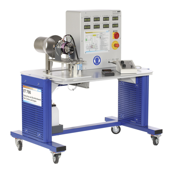
- Page 1 Experiment Instructions ET 796 Gas Turbine Jet Engine...
- Page 3 ET 796 GAS TURBINE JET ENGINE Experiment Instructions Last modification by: Dipl.-Ing. J.Boxhammer This manual must be kept by the unit. Before operating the unit: - Read this manual. - All participants must be instructed on handling of the unit and, where appropriate, on the necessary safety precautions.
- Page 4 ET 796 GAS TURBINE JET ENGINE...
-
Page 5: Table Of Contents
ET 796 GAS TURBINE JET ENGINE Table of Contents Introduction ..........1 Safety . - Page 6 ET 796 GAS TURBINE JET ENGINE 3.7.3 Starting the gas turbine up ......39 3.7.4 Operating the gas turbine .
- Page 7 ET 796 GAS TURBINE JET ENGINE 6.5 List of identification letters used in the process schematic ..74 6.6 Tables and graphs........75...
- Page 8 ET 796 GAS TURBINE JET ENGINE...
-
Page 9: Introduction
ET 796 GAS TURBINE JET ENGINE Introduction The ET 796 trainer is used to demonstrate and study the function and behaviour of a gas turbine in the model scale. Gas turbine plants are used to generate mechanical and electrical energy: –... - Page 10 ET 796 GAS TURBINE JET ENGINE The system has a simple construction and is designed specifically for educational purposes. The operation and display of all important process parameters is summarised on a control panel. The PC-based measurement data acquisition with evaluation software allows online logging of all relevant process variables and their graphical representation.
-
Page 11: Safety
ET 796 GAS TURBINE JET ENGINE Safety Intended use The unit is to be used only for teaching purposes. Structure of safety instructions The signal words DANGER, WARNING or CAUTION indicate the probability and potential severity of injury. An additional symbol indicates the nature of the hazard or a required action. - Page 12 ET 796 GAS TURBINE JET ENGINE Symbol Explanation Electrical voltage Hazard area (general) Hot surface Wear ear defenders No naked light No smoking Oxidizing Flammable Toxic Notice 2 Safety...
-
Page 13: Safety Instructions
ET 796 GAS TURBINE JET ENGINE Safety instructions The following instructions must be observed to ensure safe and reliable operation of the device. All persons concerned with the device, especially students, must be familiarised with the safety instructions. The attached operating instructions for the model gas turbine must be carefully observed. - Page 14 ET 796 GAS TURBINE JET ENGINE WARNING The gas turbine housing, exhaust stack and any of the gas turbine's exhaust ducts become very hot during operation. Risk of burns. • Do not touch any parts • Leave parts to cool down WARNING Exhaust jet is very hot (200...300°C).
- Page 15 ET 796 GAS TURBINE JET ENGINE WARNING It should always be ensured that nobody is present in the gas turbine's operating plane when the turbine is operating. Danger area. • Either stand in front of or behind the gas tur- bine, but not to the side of it.
- Page 16 ET 796 GAS TURBINE JET ENGINE WARNING Do not allow any combustible materials to come into contact with the hot exhaust pipe or to get into the exhaust jet. Risk of fire. • A wide zone around the outlet area must be kept free of combustible or heat-sensitive materials.
- Page 17 ET 796 GAS TURBINE JET ENGINE WARNING Smoking or open flames when handling com- bustible fuels can lead to explosion or defla- gration. Possibility of severe injuries. • No open flame • No smoking • Erect warning sign • Comply with relevant statutory provisions when transporting and storing fuels (kerosene, petro- leum, etc.).
- Page 18 ET 796 GAS TURBINE JET ENGINE WARNING When handling fuel, drops of fuel could get into the eyes. Risk of injury to the eyes. • Wear safety goggles If fuel gets into the eyes: • Rinse eyes immediately • Seek immediate medical attention...
- Page 19 ET 796 GAS TURBINE JET ENGINE NOTICE Fuel must be mixed with turbine oil to lubricate the turbine bearings. Only use suitable synthetic oils as specified in the appendix. NOTICE The gas turbine must be overhauled every 50 operating hours. This work must be carried out by the gas turbine manufacturer JET-CAT.
-
Page 20: Ambient Conditions For The Operating And Storage Location
ET 796 GAS TURBINE JET ENGINE Ambient conditions for the operating and storage location • Enclosed space • Free from dirt and humidity • Level and fixed surface 2 Safety... -
Page 21: Description Of The Device
ET 796 GAS TURBINE JET ENGINE Description of the device Electronic AUX channel Control Unit Throttle Throttle trim Jet-tronic remote GSU inlet Exhaust gas outlet 1 Compressor Electronic control unit 2 Combustion chamber 3 Turbine Glow plug 4 Jet nozzle... -
Page 22: Design Of The Trainer
ET 796 GAS TURBINE JET ENGINE The trainer includes a complete gas turbine sys- tem with the following sub-systems: – Model gas turbine consisting of compressor (1), combustion chamber (2), turbine (3) and jet nozzle (4) with means for thrust measurement (5). -
Page 23: Device Design
ET 796 GAS TURBINE JET ENGINE Device design Fig. 3.2 Front view Fuel tank Gas turbine outlet temperature T3 GSU (Ground Support Unit) Combustion chamber pressure P1 Operating unit Combustion chamber temperature T2 USB connector for the PC Fuel consumption F2... -
Page 24: Process Schematic
ET 796 GAS TURBINE JET ENGINE Process schematic Operating unit Jet-tronic remote GSU (Ground Support Unit) AUX channel Throttle Throttle trim ECU/ Electronic Control Unit (in control cabinet) Fuel tank Fuel pump Combustion chamber Compressor Turbine Starter motor Exhaust gas... -
Page 25: Components Of The Trainer
ET 796 GAS TURBINE JET ENGINE Components of the trainer 3.4.1 Gas turbine Fig. 3.4 Gas turbine P80-SE The model gas turbine forms the core of the system. It consists of an axial turbine with direct- coupled radial compressor and an annular com- bustion chamber. - Page 26 ET 796 GAS TURBINE JET ENGINE (1) (35000...115000 min ). Here, the velocity of the air is converted into pressure. Fig. 3.5 Section model of a JetCat gas turbine Fig. 3.6 Model gas turbine 3 Description of the device...
- Page 27 ET 796 GAS TURBINE JET ENGINE A portion of the air is branched off at the entrance to the combustion chamber (3) and fed to the flame tube (4) at the end. The liquid fuel enters the evaporator pipes (5) from the rear. Here the fuel is...
- Page 28 ET 796 GAS TURBINE JET ENGINE The exhaust jet draws in additional secondary air through the injector effect. This mixes with the exhaust jet in the mixing tube (Fig. 3.10-9) and decreases the outlet temperature. The entire gas turbine with the thrust table (Fig.
- Page 29 ET 796 GAS TURBINE JET ENGINE Fig. 3.11 Gas turbine on the movably mounted thrust table Force sensor Safety limit switch Hose coupling for venting the main fuel line 4a - (see Fig. 3.4) Hose coupling for bleeding the start fuel line...
-
Page 30: Fuel System
ET 796 GAS TURBINE JET ENGINE 3.4.2 Fuel system Kerosene or petroleum are used as fuel. Some turbine oil is mixed into the fuel to lubricate the tur- bine bearing (ratio of 1:20). The turbine has a low pressure system with an evaporator. An electric fuel pump pumps the fuel into the turbine's evap- orator tubes. -
Page 31: Starting And Ignition System
ET 796 GAS TURBINE JET ENGINE 3.4.3 Starting and ignition system The automatic starting system consists of a pow- erful DC motor. This drives the compressor impel- ler via an automatic cone clutch. At a certain min- imum speed of approximately 3000min... -
Page 32: Control Elements
ET 796 GAS TURBINE JET ENGINE 3.4.4 Control elements All indicators and connectors, as well as the main switch and emergency stop switch are located on the control cabinet. The USB connector, the con- nector for the operating unit and the connector for the "Jet-tronic remote GSU"... - Page 33 ET 796 GAS TURBINE JET ENGINE The gas turbine is operated via the gas turbine's operating unit. This houses the electronic control unit's status indicators (1) and the controls required for operation. The Throttle slider is used to set the gas turbine's power output. The gas tur- bine can be turned off using the Throttle Trim switch.
- Page 34 ET 796 GAS TURBINE JET ENGINE Connecting the (Jet-tronic) display and program- ming unit provides additional useful information about the status of the gas turbine via the "Jet- tronic remote GSU" display. Connecting the Jet- tronic is not essential for operation of the gas tur- bine.
-
Page 35: Measurement Data Acquisition
ET 796 GAS TURBINE JET ENGINE Measurement data acquisition 3.5.1 Program installation Required for installation: • A ready-to-use PC with USB port (for minimum requirements see Chapter 6.1). • G.U.N.T. CD-ROM All components required to install and operate the program are included on the CD-ROM pro- vided by GUNT. -
Page 36: Program Operation
3.5.2 Program operation • Select the program and run it via: Start / Programs / G.U.N.T. / ET 796 • When you start the software for the first time after installation you are prompted to select the desired language for the program operation. -
Page 37: Setting Up The Gas Turbine
ET 796 GAS TURBINE JET ENGINE Setting up the gas turbine 3.6.1 Checking the gas turbine Before the gas turbine is operated for the first time, it must be checked for transport damage and misalignment. If training or initial commissioning was also ordered through G.U.N.T., then this check is car-... -
Page 38: Installation
ET 796 GAS TURBINE JET ENGINE 3.6.2 Installation Due to the high requirement for fresh air (approx. 800m /h) the gas turbine may only be operated in large, well-ventilated spaces. Lead the exhaust gases directly to the outside or connect an exhaust line. - Page 39 – Connect the electrical power supply. Plug the USB cable provided for computer-based meas- urement data acquisition in to the ET 796 device and connect to the PC. See installation instructions relating to the installation of hard- ware and software.
-
Page 40: Operating The Gas Turbine
ET 796 GAS TURBINE JET ENGINE Operating the gas turbine 3.7.1 Preparations for start The following tasks must be performed before starting the gas turbine: – Check fuel level. If topping up the fuel level, make sure the appropriate turbine oil is added (see Page 69). -
Page 41: Bleeding The Fuel Lines With The Kerosene Start System
ET 796 GAS TURBINE JET ENGINE 3.7.2 Bleeding the fuel lines with the kerosene start system Before the first start and whenever the kerosene lines are empty or contain air bubbles (e.g. fuel tank empty during operation), the system must be bled. -
Page 42: Bleeding The Fuel Supply To The Engine
ET 796 GAS TURBINE JET ENGINE 3.7.2.2 Bleeding the fuel supply to the engine: 1. First remove the 4 mm main fuel line (Fig. 3.11, Page 21, no. 3) from the gas turbine and lead to a collecting tank. If this isn't done, the follow- ing procedure will flood the gas turbine with fuel (->... -
Page 43: Bleeding The Fuel Supply To The Kerosene Start System
ET 796 GAS TURBINE JET ENGINE 3.7.2.3 Bleeding the fuel supply to the kerosene start system: 1. First, bleed the fuel supply to the engine (see Chapter 3.7.2.2, Page 34). The fuel tank must be filled. 2. Disconnect glow plug connector. Failure to do so will damage the seals due to the heat. - Page 44 ET 796 GAS TURBINE JET ENGINE bit of fuel until the Teflon hose is also filled and kerosene is present right at the kerosene igniter. The fuel supply to the kerosene start system has now been bled. 3 Description of the device...
-
Page 45: Testing And Adjusting The Fuel Pump Power
ET 796 GAS TURBINE JET ENGINE 3.7.2.4 Testing and adjusting the fuel pump power When adjusting the amount of fuel, check and adjust the hose line to the gas turbine's fuel sup- ply, not the fuel supply to the kerosene start sys- tem. - Page 46 ET 796 GAS TURBINE JET ENGINE "Set" button. The ECU stores the value and returns to the RUN menu. 7. Reconnect the fuel line to the gas turbine. 3 Description of the device...
-
Page 47: Starting The Gas Turbine Up
ET 796 GAS TURBINE JET ENGINE 3.7.3 Starting the gas turbine up Gas turbines are started up in a fixed start-up pro- cedure. This is typical of all gas turbines. Differ- ences are only due to varying degrees of automa- tion. - Page 48 – Set Throttle to idle (min). Fig. 3.22 Fold the gas turbine to remove remaining fuel – Switch on ET 796 at the main switch. – Switch AUX channel to "run". The three LEDs flash in sequence. – Start the automatic start-up process by moving the throttle to full throttle (max).
-
Page 49: Operating The Gas Turbine
ET 796 GAS TURBINE JET ENGINE Gas turbine automatic start process – The starter motor brings the turbine to the start- ing speed (yellow LED is on). – Starting fuel is added via the glow plug, so that the gas turbine ignites. Ignition can be detected by an increase in temperature and speed. -
Page 50: Shutting Down The Gas Turbine
ET 796 GAS TURBINE JET ENGINE 3.7.5 Shutting down the gas turbine The gas turbine is shut down via the gas turbine's AUX channel. – Regular shutdown via the "Auto off" position. The turbine runs at 50 000...60 000min for a short period. -
Page 51: Maintenance
ET 796 GAS TURBINE JET ENGINE Maintenance 3.8.1 Glow plug If there are problems starting up, check the glow plug for damage, short circuit or dirt. A burnt-out glow plug is detected and displayed by the elec- tronic control unit. Replacing or loosening the glow plug: –... -
Page 52: Servicing The Gas Turbine
ET 796 GAS TURBINE JET ENGINE 3.8.2 Servicing the gas turbine The manufacturer recommends servicing the gas turbine after 50 hours of operation. The turbine bearings are replaced during this service. Manufacturer of gas turbine model: JetCat P80 Ing.Büro CAT M.Zipperer GmbH... -
Page 53: Faults And Troubleshooting
ET 796 GAS TURBINE JET ENGINE Faults and troubleshooting This section describes any problems that may occur with the system and their causes. Gas turbine specific faults and the meaning of the error messages can be found in the gas turbine manufacturer's manual. -
Page 54: Decommissioning
ET 796 GAS TURBINE JET ENGINE Gas turbine fails to start No reaction with the AUX channel in the "Run" – Main switch not turned on position – No mains voltage – Conductive connection between gas turbine and table No ignition –... -
Page 55: Basic Principles
ET 796 GAS TURBINE JET ENGINE Basic principles The basic principles set out in the following make no claim to completeness. For further theoretical explanations, refer to the specialist literature. Fig. 4.1 Engine from General Electric J85-GE-17A turbojet Inlet Compressor... -
Page 56: The Open Gas Turbine Cycle
ET 796 GAS TURBINE JET ENGINE The open gas turbine cycle The gas turbine trainer operates according to the open thermodynamic cycle, in which the working Fuel fluid is taken from the environment and fed back to it again. In this case, the working fluid of air is subjected to the following changes of state: –... -
Page 57: Representation In The Heat Diagram
ET 796 GAS TURBINE JET ENGINE 4.1.1 Representation in the heat diagram Representing the cycle in the heat chart, known as a T-s diagram, is useful in order to be able to better assess the conditions in the thermody- namic cycle. Here the temperature of the working fluid is plotted over the specific entropy. -
Page 58: Thermal Efficiency (Ideal)
ET 796 GAS TURBINE JET ENGINE 4.1.2 Thermal efficiency (ideal) The efficiency results from the ratio of the input heat and mechanical work. Assuming a constant heat capacity of the working fluid, for the thermal efficiency we get: ----- - –... -
Page 59: Specific Work Capacity
ET 796 GAS TURBINE JET ENGINE 4.1.3 Specific work capacity For the specific work capacity the following rela- tionship applies: 0 285 – -------------- – – (4.3) 0 285 ... -
Page 60: Representation In The P-V Diagram
ET 796 GAS TURBINE JET ENGINE 4.1.4 Representation in the p-v diagram The thermodynamic cycle can also be repre- sented in the p-v diagram. This makes the com- pression and expansion process clearly visible. Heat input q Expansion Compression Useful work Heat output q Fig. -
Page 61: Gas Turbine Jet Engine
ET 796 GAS TURBINE JET ENGINE 4.1.5 Gas turbine jet engine In aircraft engines, above a certain airspeed it is cheaper to use the exhaust jet directly for gener- ating thrust. The simplest jet propulsion consists of a single-shaft gas turbine (1) in an open ther- modynamic cycle. - Page 62 ET 796 GAS TURBINE JET ENGINE 4 Basic principles...
-
Page 63: Experiments
ET 796 GAS TURBINE JET ENGINE Experiments The selection of experiments makes no claims of completeness but is intended to be used as a stimulus for your own experiments. The results shown are intended as a guide only. Depending on the construction of the individual... -
Page 64: Conducting The Experiment
ET 796 GAS TURBINE JET ENGINE 5.1.2 Conducting the experiment – Run the turbine in the five operating points of idling, 20% partial load, 40% partial load, 60% partial load and full load. – Record the measured values either with or without a PC 5.1.3... -
Page 65: Analysis Of The Experiment
ET 796 GAS TURBINE JET ENGINE 5.1.4 Analysis of the experiment 5.1.4.1 Air mass flow and fuel mass flow · The air mass flow in kg/s is calculated as fol- lows: · ------------ - ---------------------- - Anzeige (5.1) - Page 66 ET 796 GAS TURBINE JET ENGINE · The fuel mass flow is calculated at a display of fuel consumption dV fuel/dt in L/h and a desired · fuel mass flow in kg/s as follows: · ------------ - Anzeige (5.3)
-
Page 67: Other Characteristics Of The Gas Turbine
ET 796 GAS TURBINE JET ENGINE 5.1.4.2 Other characteristics of the gas turbine Calculation based on full load operation. Specific thrust: · · · · ------ - where (5.4) · N s 97 9 N --------------------- - -----------... - Page 68 ET 796 GAS TURBINE JET ENGINE Thermal efficiency (ideal): ------------ - – – -------------- (5.8) – 0 285 ----------- - where = 1,4 p (abs.) ----------------------------- - where compression ratio (abs.) where p...
-
Page 69: Representation Of The Measured Data In Diagrams
ET 796 GAS TURBINE JET ENGINE 5.1.4.3 Representation of the measured data in diagrams The measured data can be displayed online and saved with the PC-based measurement data acquisition. Then the recorded measured values can be processed with the Measurements Graph part of the program. - Page 70 ET 796 GAS TURBINE JET ENGINE The following figure shows recorded measure- ment data in the "Measurements Graph" window. The thrust of the gas turbine is shown as a func- tion of the speed. The thrust increases dispropor- tionately with the speed. There is almost no thrust at idle speed.
- Page 71 ET 796 GAS TURBINE JET ENGINE The following figure shows the relationship between fuel consumption and thrust. Fig. 5.3 Fuel consumption as a function of thrust 5 Experiments...
- Page 72 ET 796 GAS TURBINE JET ENGINE The following figure illustrates the relationship between air demand and thrust. The tempera- tures are also shown. Fig. 5.4 Temperatures and the gas turbine's air demand as a function of thrust Compressor temp. in °C Combustion chamber temp.
- Page 73 ET 796 GAS TURBINE JET ENGINE The last diagram shows the combustion chamber pressure over the speed. This results in a quad- ratic dependency. Fig. 5.5 Combustion chamber pressure of the gas turbine from start-up to 120,000 revolutions 5 Experiments...
-
Page 74: Determining The Fuel-Air Ratio
ET 796 GAS TURBINE JET ENGINE 5.1.4.4 Determining the fuel-air ratio The fuel-air ratio is determined from the quotients of the actual amount of air taken in to the amount of air required for stoichiometric combustion of the fuel. The amount of air required for combustion of... -
Page 75: Appendix
ET 796 GAS TURBINE JET ENGINE Appendix Technical data Dimensions Length x Width x Height 1230 x 800 x 1330 mm Weight 112 kg Power supply Voltage 230 V Frequency 50 Hz Phases Rated input (power) 400 W Alternatives optional, see rating plate... - Page 76 ET 796 GAS TURBINE JET ENGINE WARNING Smoking or open flames when handling com- bustible fuels can lead to explosion or defla- gration. Possibility of severe injuries. • No open flame • No smoking • Erect warning sign • Comply with relevant statutory provisions when transporting and storing fuels (kerosene, petro- leum, etc.).
- Page 77 ET 796 GAS TURBINE JET ENGINE Lubrication system Oil-mist lubrication with oil-fuel mixture mixing ratio 1:20. Example for filling the fuel tank: 4,75L petroleum and 0,25L turbine oil. Recommended oil types: AeroShell Turbine Oil 500/560 with the specifica- tion MIL-PRF 23699 Grade HTS or Mobil Jet 1.
- Page 78 ET 796 GAS TURBINE JET ENGINE Pressure sensors and digital display – Combustion chamber pressure: 0... 2 bar Mass flows – Air inlet measuring nozzle with square root extracting pressure sensor and digital display: 0...500 L/s – Fuel from the fuel pump Control: 0...25 L/h...
-
Page 79: List Of Abbreviations
ET 796 GAS TURBINE JET ENGINE List of abbreviations Abbreviation Meaning Electronic Control Unit Ground Support Unit · dV_fuel/dt Fuel consumption · dV_air/dt Air flow List of formula symbols and units Formula symbol Mathematical/physical value Unit N s ... - Page 80 ET 796 GAS TURBINE JET ENGINE Formula symbol Mathematical/physical value Unit Specific heat output J/kg · Output thermal power W, kW Specific entropy kg K Thrust Time h:m:s Temperature under standard conditions °C, K Ambient temperature °C, K...
-
Page 81: List Of Symbols In The Process Schematic
ET 796 GAS TURBINE JET ENGINE List of symbols in the process schematic Symbol Description Fuel pump Fuel tank Filter Motor Fuel valve Combustion chamber Compressor Turbine Measuring nozzle 6 Appendix... - Page 82 ET 796 GAS TURBINE JET ENGINE List of identification letters used in the process schematic Identifi- Description cation letter Equipment and machinery Container, tank, hopper, silo Electric motor Pump Compressor, vacuum pump, fan Fittings Valve, general Tab. 6.1 Identification letters for equipment, machinery, fittings and pipes...
- Page 83 ET 796 GAS TURBINE JET ENGINE Tables and graphs Unit 0,001 0,000001 0,000000001 1.000 0,001 0,000001 1.000.000 1.000 0,001 1.000.000.000 1.000.000 1.000 Tab. 6.3 Conversion table for units of volume Unit L/min /min 1L/s 3600 0,06 1L/min 0,01667 0,001 0,06...
- Page 84 ET 796 GAS TURBINE JET ENGINE Worksheets Gas turbine experiment Date: Ambient temperature T °C: Air pressure p in mbar: Rel. humidity in %: Experiment no.: Compressor outlet T in °C Combustion chamber T in °C Turbine outlet T in °C...
Need help?
Do you have a question about the ET 796 and is the answer not in the manual?
Questions and answers