Table of Contents
Advertisement
Quick Links
Advertisement
Table of Contents

Subscribe to Our Youtube Channel
Related Manuals for Moravian Instruments C2 Series

Summary of Contents for Moravian Instruments C2 Series
- Page 1 C2 Series Astronomical Cameras User’s Guide...
- Page 2 Version 1.6 Modified on October 13 , 2023 All information furnished by Moravian Instruments is believed to be accurate. Moravian Instruments reserves the right to change any information contained herein without notice. C2 cameras are not authorized for and should not be used within Life Support Systems without the specific written consent of the Moravian Instruments.
-
Page 3: Table Of Contents
Table of Contents Introduction ....................5 C2 Camera Overview ..................7 C2 Camera System ..................9 C2 with global shutter CMOS Sensors ............11 Camera Electronics .................. 12 Sensor linearity ..................13 Download speed ..................14 Camera gain .................... 15 Conversion factors and read noise ............ - Page 4 Overheating protection ............... 29 Power supply ................... 29 Mechanical Specifications ................32 Camera with Internal Filter Wheel ............34 Camera with “XS” External Filter Wheel ..........35 Camera without filter wheel ..............36 Back focal distance .................. 37 Adapters without back focal distance defined ........38 Adapters with defined back focal distance .........
-
Page 5: Introduction
Mechanical design of this series inherits from earlier CCD-based G2 Mark II cameras, which makes the C2 series fully compatible with vast range of telescope adapters, off-axis guider adapters, internal or external filter wheels, Camera Ethernet adapters, guiding cameras etc. - Page 6 C2 cameras are designed to be attached to host PC through very fast USB 3.0 port. While C2 cameras remain compatible with older (and slower) USB 2.0 interface, image download time is significantly longer. Alternatively, it is possible to use the “Moravian Camera Ethernet Adapter” device.
-
Page 7: C2 Camera Overview
C2 Camera Overview C2 camera head is designed to be easily used with a set of accessories to fulfil various observing needs. Camera head itself is manufactured in two different variants: Camera with Internal filter wheel. Camera with control port for External filter wheel. This model allows attachment of several variants of external filter wheels with various number of filter positions and sizes. - Page 8 Extra small “XS” size wheel for 8 unmounted filters D31 mm or filters in 1.25” threaded cells. Extra small “XS” size wheel for 7 unmounted filters D36 mm. Small “S” size wheel for 12 unmounted filters D31 mm or filters in 1.25”...
-
Page 9: C2 Camera System
C2 Camera System Figure 2: Schematic diagram of C2 camera system components... - Page 10 Components of the C2 Camera system include: 1. C2 camera head with Internal Filter Wheel (5 or 6 positions) 2. C2 camera head capable to control External Filter Wheel 3. External Filter Wheel “XS” size (7 or 8 positions) 4. External Filter Wheel “S” size (10 or 12 positions) 5.
-
Page 11: C2 With Global Shutter Cmos Sensors
C2 with global shutter CMOS Sensors C2 series of CMOS cameras with Sony IMX global shutter CMOS detectors have pixel size 3.45 × 3.45 μm or 4.50 × 4.50 μm. Three lines of C2 cameras with global shutter are available depending on... -
Page 12: Camera Electronics
C2 camera models with 3.45 × 3.45 μm pixels and 8- and 12-bit digitization: Model C2-3000 C2-5000 C2-12000 CMOS sensor IMX252 IMX250 IMX253 Resolution 2064 × 1544 2464 × 2056 4112 × 3008 Pixel size 3.45 × 3.45 μm 3.45 × 3.45 μm 3.45 ×... -
Page 13: Sensor Linearity
Sensor linearity The sensors used in C2 cameras show very good linearity in response to light. This means the camera can be used for advanced research projects, like the photometry of variable stars and transiting exoplanets etc. Figure 3: Response of the Sony IMX sensors with 3.45 × 3.45 μm pixels (IMX252) Figure 4: Response of the Sony IMX sensors with 4.50 ×... -
Page 14: Download Speed
Download speed As already noted, there are two lines of C2 camera series, differing in the used sensor. The first series with 3.45 × 3.45 μm pixels offers four different read modes: 8-bit slow mode with ~132 MPx/s digitization speed ... -
Page 15: Camera Gain
Also, standard format for image storage in astronomy is FITS. While this format supports 8-bit per pixel, this variant is rather unusual and 16 or 32-bit integer or 32-bit floating-point pixels are typically stored to disk files to achieve as wide compatibility as possible. Camera gain Sensors used in C2 cameras offer programmable gain from 0 to 24 dB, which translates to the output signal multiplication from 1×... -
Page 16: Exposure Control
software package. Results may slightly vary depending on the test run, on the particular sensor and other factors (e.g. sensor temperature, sensor illumination conditions etc.), but also on the software used to determine these values, as the method is based on statistical analysis of sensor response to light. -
Page 17: C2 With Rolling Shutter Cmos Sensors
C2 with rolling shutter CMOS Sensors C2 series of CMOS cameras with Sony IMX rolling shutter CMOS detectors currently contain single model with Sony IMX533 sensor with pixel size 3.76 × 3.76 μm: Model C2-9000 CMOS sensor IMX533 Resolution 3008 × 3008 Pixel size 3.76 ×... -
Page 18: Download Speed
Figure 5: Response of the Sony IMX rolling-shutter sensor (IMX533) Download speed Thanks to C2-9000 onboard RAM, downloading of the image to the host computer does not influence image digitization process, as the download only transfers already digitized images from camera memory. Time needed to digitize and download single full frame depends on USB connection type. -
Page 19: Camera Gain
The driver is sometimes forced to read bigger portions of the sensor than the user defined because of a sub-frame position and dimension limitations imposed by the sensor hardware. Sometimes it is even necessary to read a whole sensor. It is recommended to click the Adjust Frame button in the Frame tab of the SIPS camera control tool. -
Page 20: Conversion Factors And Read Noise
represent gain in dB nor in multiply value. However, the driver offers a function, which transforms the gain numerical value to gain expressed in dB as well as multiply. Some selected values are shown in the table: Gain number Gain in dB Gain multiply 0.00 1.00×... -
Page 21: Hardware Binning
performed only in the camera driver (software binning) and does not rely on the limited capabilities of the hardware binning. The negative side of software binning is the same download time like in the case of full-resolution 1×1 mode. For typical astronomy usage, the small fraction of second download time is irrelevant, but for applications sensitive to download time, the hardware 2×2 binning can be useful. - Page 22 ( √ 2) × ( √ 2) . Resulting S/N increases 2-times, but only until the sum of all pixels is lower than the pixel capacity. If we average 4 pixels, signal remains the same but the noise is ( √...
-
Page 23: Binning In Photometry
Binning in photometry Saturated pixels within bright stars are no issue for aesthetic astro- photography, but photometry measurement is invalid if any pixel within the measured object reaches maximum value, because it is not possible to determine the amount of lost flux. Software performing photometry (e.g. the SIPS Photometry tool) should detect saturation value and invalidate entire photometric point not to introduce errors. -
Page 24: Mechanical Shutter
There is no theoretical limit on maximal exposure length, but the longest exposures are limited by saturation of the sensor either by incoming light or by dark current (see the following chapter about sensor cooling). Mechanical shutter Mechanical shutter of the C2-9000 camera works the same way like in the case of global-shutter C2 variants. - Page 25 Figure 6: SIPS offers GUI to determine the state the GPS receiver Determination of exact exposure time is quite complicated because of the rolling-shutter nature of the used sensors. Camera driver does all the calculations and returns the time of the start of exposure of the first line of the image.
- Page 26 desired sub-frame and then crops it by software. The provided start exposure time then concerns the first line actually read from the camera, not the first line of the resulting (software cropped) image. For instance, the y-coordinate of the sub-frame must not be lower than 15 lines.
-
Page 27: Cooling And Power Supply
Cooling and power supply Regulated thermoelectric cooling is capable to cool the CMOS sensor up to 40 °C below ambient temperature. The Peltier hot side is cooled by fan. The sensor temperature is regulated with ±0.1 °C precision. High temperature drop and precision regulation ensure very low dark current for long exposures and allow proper image calibration. - Page 28 The cooling performance also depends on the environmental conditions and also on the power supply. If the power supply voltage drops below 12 V, the maximum temperature drop is lower. CMOS sensor cooling Thermoelectric (Peltier modules) Maximal cooling ΔT ~40 °C below ambient (~95% cooling) Regulated cooling ΔT 35 °C below ambient (~90% cooling) Regulation precision...
-
Page 29: Overheating Protection
Overheating protection The C2 cameras are equipped with an overheating protection in their firmware. This protection is designed to prevent the Peltier hot side to reach temperatures above ~50°C – sensor cooling is turned off to stop heat generation by the hot side of the Peltier TEC modules. Please note the overheating protection uses immediate temperature measurement, while the value of camera temperature, presented to the user, shows temperature averaged over a longer period. - Page 30 Warning: The power connector on the camera head uses center-plus pin. Although all modern power supplies use this configuration, always make sure the polarity is correct if you use own power source. Camera head supply 12 V DC Camera head power consumption <4 W without cooling 26 W maximum cooling Power connector...
- Page 31 Figure 9: 12 V DC/5 A power supply adapter for C2 camera...
-
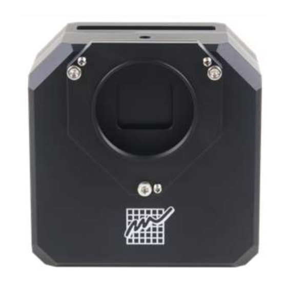
Page 32: Mechanical Specifications
Mechanical Specifications Compact and robust camera head measures only 114×114×65 mm (approx. 4.5×4.5×2.6 inches). The head is CNC-machined from high-quality aluminum and black anodized. The head itself contains USB-B (device) connector and 12 V DC power plug. Integrated mechanical shutter allows streak-free image readout, as well as automatic dark frame exposures, which are necessary for unattended, robotic setups. - Page 33 Back focal distance 33.5 mm (base of adjustable adapters) Camera head weight 1.15 kg (with Internal filter wheel) 1.00 kg (without filter wheel) 1.70 kg (with “XS” External filter wheel) 1.95 kg (with “S” External filter wheel) C2 cameras use electronic shuttering to control exposures. Mechanical shutter is used only to cover the sensor when acquiring dark or bias frames.
-
Page 34: Camera With Internal Filter Wheel
Camera with Internal Filter Wheel Figure 11: C2 camera head front view dimensions Figure 12: C2 camera head with Internal Filter Wheel side view dimensions... -
Page 35: Camera With "Xs" External Filter Wheel
Figure 13: C2 camera head bottom view dimensions Camera with “XS” External Filter Wheel Figure 14: C2 camera head with External filter wheel front view dimensions... -
Page 36: Camera Without Filter Wheel
Figure 15: C2 camera head with External filter wheel side view dimensions Figure 16: C2 camera head with External filter wheel bottom view dimensions The “S” sized External Filter Wheel diameter is greater (see External Filter Wheel User's Guide), but the back focal distance of all external filter wheels is identical. -
Page 37: Back Focal Distance
Figure 17: Camera without filter wheel with "thin" adapter base “Thick” adapter base has the same thickness like the External filter wheel. This means all adapters, attached to this thick base, keep the same 33.5 mm back focal distance like the camera with External filter wheel attached or camera with Internal filter wheel and “thin”... -
Page 38: Adapters Without Back Focal Distance Defined
glass, ...), fixed in the camera body. So, stated values are not mechanical, but optical back focal distances. However, no corrections for filters are included, as the thicknesses of various filters are very different. C2 cameras are manufactured in many variants and can be connected with various accessories, which leads to many possible back focal distance values. - Page 39 Figure 19: C2 camera with “S” adapter base back focal distances with short M48 × 0.75 adapter Figure 20: C2 camera with Internal Filter Wheel and “S” adapter base back focal distances with short M48 × 0.75 adapter Figure 21: C2 camera with “XS” External Filter Wheel back focal distances with short M48 ×...
-
Page 40: Adapters With Defined Back Focal Distance
Adapters with defined back focal distance There are three basic variants of C2 camera, differing with back focal distance of the camera head front shell — camera without internal filter wheel, with Internal Filter Wheel with External Filter Wheel. But adapters preserving back focal distance are always designed with the same thickness. -
Page 41: Off-Axis Guider Adapter
Figure 23: C2 camera with Internal filter wheel, the Canon EOS adapter is on the thin adapter base to preserve defined BFD Figure 24: C2 camera with External filter wheel, the Canon EOS adapter is attached to adapter base on the External filter wheel Off-Axis Guider Adapter The OAG for C2 cameras uses M42×0.75 or M48×0.75 threaded adapter with 55 mm back focal distance. - Page 42 Figure 25: C2 camera without filter wheel, the OAG is on the thick adapter base to preserve defined BFD (the thick adapter base adds the same BFD like the External filter wheel) Figure 26: C2 camera with Internal filter wheel, the OAG is on the thin adapter base to preserve defined BFD...
- Page 43 Figure 27: C2 camera with External filter wheel, the OAG is attached to adapter base on the External filter wheel...
-
Page 44: Optional Accessories
Optional accessories Various accessories are offered with C2 cameras to enhance functionality and help camera integration into imaging setups. Telescope adapters Various telescope and lens adapters for the C2 cameras are offered. Users can choose any adapter according to their needs and other adapters can be ordered separately. - Page 45 Figure 28: Position of the OAG reflection mirror relative to optical axis C2-OAG is manufactured in two variants, one with M42×0.75 thread (T- thread) and another with M48×0.75 thread. Both variants are designed to be compatible with external filter wheels and to preserve 55 mm distance from the sensor.
-
Page 46: Gps Receiver Module
OAG guider port is compatible with CMOS based C1 cameras or older CCD based G0 and G1 cameras. It is necessary to replace the CS/1.25” adapter with short, 10 mm variant in the case of G1 cameras. Because C1 cameras follow CS-mount standard, (BFD 12.5 mm), any camera following this standard with 10 mm long 1.25”... -
Page 47: Gps Receiver Module Handling
Figure 30: The C2 camera with GPS receiver module with external antenna Please note the camera must be equipped with a different back shell as well as internal electronic circuits to be compatible with GPS modules. So, it is necessary to choose GPS-ready variant upon camera ordering. -
Page 48: Attaching Camera Head To Telescope Mount
location data are also available to the control software through specific commands. Attaching camera head to telescope mount C2 camera heads are equipped with “tripod” thread (0.25”) as well as four M4 threaded holes on the top side of the camera head. Figure 31: Threaded mounting holes on the camera head top side These threaded holes can be used to attach 1.75 inch “dovetail bar”... -
Page 49: Camera Head Color Variants
Figure 32: 1.75" bar for standard telescope mounts Camera head color variants Camera head is available in several color variants of the center plate. Visit manufacturer's web pages for current offering. Figure 33: C2 camera color variants Camera Ethernet Adapter Camera Ethernet Adapter allows connection of up to 4 Cx and Gx cameras of any type on the one side and 1 Gbps Ethernet on the other side. - Page 50 adapter allows access to connected cameras using routable TCP/IP protocol over practically unlimited distance. Figure 34: The Camera Ethernet Adapter with two connected cameras...
-
Page 51: Adjusting Of The Telescope Adapter
Adjusting of the telescope adapter All telescope/lens adapters of the C2 series of cameras can be slightly tilted. This feature is introduced to compensate for possible misalignments in perpendicularity of the telescope optical axis and sensor plane. Figure 35: Releasing of the “pushing” screw The Mark II camera telescope adapters are attached using three “pulling”... - Page 52 Because the necessity to adjust two screws (one pushing, one pulling) at once is inconvenient, the adapter tilting mechanism is also equipped with ring-shaped spring, which pushes the adapter out of the camera body. This means the pushing screws can be released and still slight releasing of the pulling screw means the distance between the adapter and the camera body increases.
- Page 53 Adjustable telescope/lens adapters are attached slightly differently depending if the adapter is attached directly to the camera head (e.g. when camera is equipped with internal filter wheel) or to the External filter wheel case. C2 camera adapters are not mounted directly on the camera head.
-
Page 54: Camera Maintenance
Camera Maintenance The C2 camera is a precision optical and mechanical instrument, so it should be handled with care. Camera should be protected from moisture and dust. Always cover the telescope adapter when the camera is removed from the telescope or put the whole camera into protective plastic bag. Desiccant exchange The C2 camera cooling is designed to be resistant to humidity inside the CMOS sensor chamber. -
Page 55: Exchanging The Silica-Gel
silica-gel type (manufacturer). It is recommended to shorten replacement interval if the silica-gel is completely green or transparent upon replacement. If it is still yellow-orange, it is possible to prolong the replacement interval. Figure 38: Silica-gel container is accessible from the camera back side Exchanging the silica-gel C2 cameras employ the same desiccant container like the larger C1+, C1x, C3 and C4 cameras as well as the cooled Gx CCD cameras. - Page 56 aluminum parts only. So, it is possible to heat the whole container to desired temperature without risking of the temperature-induced sealing damage. Figure 39: Desiccant is held inside container by perforated cap Note: New containers have a thin O-ring close to the threaded edge of the container.
-
Page 57: Changing Filters
The sealing cap as well as the tool-less container are not supplied with the camera, they are supplied only as optional accessory. Figure 40: Optional cap, standard container and the tool-less variant of the container Changing Filters It is necessary to open the camera head to change filters or the whole filter wheel. -
Page 58: Changing The Whole Filter Wheel
bar, plugged into the electronics board. It is not necessary to unplug these cables to change filters, but if you unplug them, take care to connect them again in the proper orientation! Figure 41: Filters can be exchanged after removing of the camera front cover Changing the Whole Filter Wheel The whole filter wheel can be changed at once. -
Page 59: Power Supply Fuse
Warning: Both pulling and pushing screws, used on the C2 camera adapter, are fine-pitch M4×0.5 thread screws, not standard M4 thread ones. Always use only screws supplied with the adapter, using of normal M4 screws damages the adapter. Always make sure to carefully locate the ring-shaped spring prior to attaching the adapter. - Page 60 the camera does not work when the camera is connected to proper power supply (12 V DC, center + plug), return the camera to the service center for repair.
Need help?
Do you have a question about the C2 Series and is the answer not in the manual?
Questions and answers