Table of Contents
Advertisement
Quick Links
Advertisement
Table of Contents

Related Manuals for Moravian Instruments C1+ Series

Summary of Contents for Moravian Instruments C1+ Series
- Page 1 C1+ Series Cooled CMOS Cameras User’s Guide...
- Page 2 Version 1.1 Modified on September 2 , 2020 All information furnished by Moravian Instruments is believed to be accurate. Moravian Instruments reserves the right to change any information contained herein without notice. C1+ cameras are not authorized for and should not be used within Life Support Systems without the specific written consent of the Moravian Instruments.
-
Page 3: Table Of Contents
Table of Contents Introduction ....................5 C1+ Camera Overview ................... 8 C1+ Camera System .................. 9 CMOS Sensors and Camera Electronics ............11 Camera Electronics .................. 12 Sensor linearity ................... 13 Download speed ................. 14 Camera gain ..................15 Conversion factors and read noise ............15 Exposure control ................. - Page 4 Camera Maintenance .................. 35 Desiccant exchange ................. 35 Exchanging the silica-gel..............36 Changing the telescope adapter ............. 38 Changing the C1 compatible adapter ..........38 Changing the C2 compatible adapter ..........38...
-
Page 5: Introduction
Introduction Thank you for choosing the Moravian Instruments camera. C1+ camera models are designed to fulfil the gap between small and lightweight C1 models, intended as Moon and planetary cameras and auto-guiders, and C2 cameras, equipped with active sensor cooling and mechanical shutter and thus intended for more serious astronomical imaging and research. - Page 6 Rich software and driver support allows usage of C1+ camera without necessity to invest into any 3 party software package thanks to included free SIPS software package. However, ASCOM (for Windows) and INDI (for Linux) drivers, shipped with the camera, provide the way to integrate C1+ camera with broad variety of camera control programs.
- Page 7 Please note while the USB standard allows usage of cable no longer than approx. 5 meters, the TCP/IP communication protocol used to connect the camera over the Ethernet adapter is routable, so the distance between camera setup and the host PC is virtually unlimited. Download speed is naturally significantly slower when camera is attached over Ethernet adapter, especially when compared with direct USB 3 connection.
-
Page 8: C1+ Camera Overview
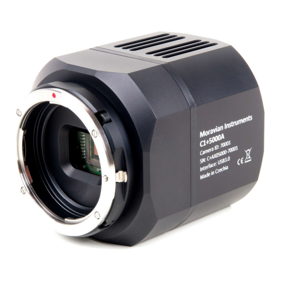
C1+ Camera Overview C1+ camera head is designed to be as small and compact as a cooled camera with rich features and compatible with broad set of accessories can be. C1+ cameras are equipped with tiltable telescope interface and tripod mounting threaded holes. -
Page 9: C1+ Camera System
Extra small “XS” size wheel for 8 unmounted filters D31 mm or filters in 1.25” threaded cells. Extra small “XS” size wheel for 7 unmounted filters D36 mm. Small “S” size wheel for 12 unmounted filters D31 mm or filters in 1.25”... - Page 10 Components of the C2 Camera system include: 1. C1+ camera with C1 compatible adapter 2. C1+ camera with C2 compatible adapter When used without spring and pushing screws, this adapter also works as base for External filter wheels. 3. External Filter Wheel “XS” size (7 or 8 positions) 4.
-
Page 11: Cmos Sensors And Camera Electronics
CMOS Sensors and Camera Electronics C1+ series of CMOS cameras are equipped with Sony IMX global shutter CMOS detectors with 3.45 × 3.45 μm or 4.50 × 4.50 μm square pixels. All used sensors utilize global electronic shutter, which means every pixel within the image is exposed in the same time, as opposed to rolling shutter, which exposes individual lines one after another. -
Page 12: Camera Electronics
C1+ camera models with 3.45 × 3.45 μm pixels and 8- and 12-bit digitization: Model C1+3000 C1+5000 C1+12000 CMOS sensor IMX252 IMX250 IMX253 Resolution 2064 × 1544 2464 × 2056 4112 × 3008 Pixel size 3.45 × 3.45 μm 3.45 × 3.45 μm 3.45 ×... -
Page 13: Sensor Linearity
Sensor linearity The sensors used in C1+ cameras show very good linearity in response to light. This means the camera can be used also for entry-level research projects, like for instance photometry or brighter variable stars etc. Figure 4: Response of the Sony IMX sensors with 3.45 × 3.45 μm pixels (IMX252) Figure 5: Response of the Sony IMX sensors with 4.50 ×... -
Page 14: Download Speed
Download speed As already noted, there are two lines of C1+ camera series, differing in the used sensor. The first series with 3.45 × 3.45 μm pixels offers four different read modes: 8-bit slow mode with ~132 MPx/s digitization speed ... -
Page 15: Camera Gain
Also, standard format for image storage in astronomy is FITS. While this format supports 8-bit per pixel, this variant is rather unusual and 16 or 32-bit integer or 32-bit floating-point pixels are typically stored to disk files to achieve as wide compatibility as possible. Camera gain Sensors used in C1+ cameras offer programmable gain from 0 to 24 dB, which translates to the output signal multiplication from 1×... -
Page 16: Exposure Control
software package. Results may slightly vary depending on the test run, on the particular sensor and other factors (e.g. sensor temperature, sensor illumination conditions etc.), but also on the software used to determine these values, as the method is based on statistical analysis of sensor response to light. -
Page 17: Cooling And Power Supply
Cooling and power supply As mentioned in the introduction, C1+ cameras can operate only with USB power. Camera is then capable to acquire images and to control (guide) telescope mount via “autoguider” port. However, active sensor cooling (as well as filter wheel operation) is available only if external 12 V DC power supply is connected. - Page 18 The cooling performance depends on the environmental conditions and also on the power supply. If the power supply voltage drops below 12 V, the maximum temperature drop is lower. CMOS sensor cooling Thermoelectric (Peltier modules) Maximal cooling ΔT ~45 °C below ambient Regulated cooling ΔT 40 °C below ambient (~90% cooling) Regulation precision...
-
Page 19: Power Supply
Power supply Certain camera functions need 12 V DC power supply. Power can be sourced from batteries, wall adapters etc. Universal 100-240 V AC/50- 60 Hz, 60 W “brick” adapter is supplied with the camera. Although the camera power consumption does not exceed 25 W, the 60 W power supply ensures noise-free operation. - Page 20 Figure 8: 12 V DC/5 A power supply adapter for C1+ camera...
-
Page 21: Autoguider Port
Autoguider port A lot of astronomical telescope mounts (especially the mass-manufactured ones) are not precise enough to keep the star images perfectly round during long exposures without corrections. Cooled astronomical cameras and digital SLR cameras allow perfectly sharp and high-resolution images, so even a small irregularity in mount tracking appears as star image deformations. - Page 22 Figure 9: Standard 6-pin Autoguider Port is located close to the USB3 port on the back side of C1+ camera The Autoguider port follows the de-facto standard introduced by SBIG ST-4 autoguider. The pins have the following functions: 1. R.A. + (Right) 2.
-
Page 23: Mechanical Specifications
Mechanical Specifications Compact and robust camera head measures only 78×78×80 mm (approx. 3.1×3.1×3.2 inches). The head is CNC-machined from high-quality aluminum and black anodized. The head itself contains USB-B (device) connector, Autoguider port connector, connector for External Filter Wheel and 12 V DC power plug. The front side of the C1+ camera body is not intended for direct attachment of the telescope/lens adapter. - Page 24 Of course, this adapter can be used without External filter wheel and then it provides M48×0.75 with very short 16.5 mm BFD. Figure 10: C1+ camera with C1 compatible adapter (left) and with C2 compatible adapter (right) Head dimensions 78×78×80 mm (without adapter base) Back focal distance 18.5 mm (with C1 compatible adapter) 16.5 mm (with C2 compatible adapter)
-
Page 25: C1+ Camera With C1 Compatible Adapter
C1+ Camera with C1 compatible adapter Figure 11: C1+ camera head with C1 compatible adapter side view dimensions Figure 12: C1+ camera head with C1 compatible adapter front view dimensions C1+ Camera with C2 compatible adapter... -
Page 26: C1+ Camera With "Xs" External Filter Wheel
Figure 13: C1+ camera head with C2 compatible adapter side view dimensions Figure 14: C1+ camera head with C2 compatible adapter front view dimensions C1+ Camera with “XS” External Filter Wheel C1+ cameras can be equipped with the same external filter wheels like the C2 cameras. - Page 27 Figure 15: C1+ camera head with External filter wheel side view dimensions Figure 16: C1+ camera head with External filter wheel bottom view dimensions The “S” sized External Filter Wheel diameter is greater (see External Filter Wheel User's Guide), but the back focal distance of all external filter wheels is identical.
-
Page 28: Optional Accessories
Optional accessories Various accessories are offered with C1+ cameras to enhance functionality and help camera integration into imaging setups. Telescope adapters Telescope and lens adapters, intended for usage with C1+ cameras, are of two kinds: Adapters for C1 cameras. These adapters are mounted using M42×0.75 thread with 18.5 mm BFD. -
Page 29: Adapters For C1+ Cameras With C2 Compatible Adapter Base And External Filter Wheel
Nikon bayonet – standard Nikon lens adapter, preserves 46.5 mm back focal distance. Canon EOS bayonet – standard Canon EOS lens adapter, preserves 44 mm back focal distance. Figure 17: Adapters for C1 cameras, compatible with C1+ models Adapters for C1+ cameras with C2 compatible adapter base and external filter wheel C1+ uses the same External filter wheels like the C2 series. -
Page 30: Attaching Camera Head To Telescope Mount
Attaching camera head to telescope mount C1+ camera heads are equipped with “tripod” thread (0.25”) as well as four M4 threaded holes on the bottom side of the camera head. Figure 18: Threaded mounting holes on the camera head bottom side These threaded holes can be used to attach 1.75 inch “dovetail bar”... -
Page 31: Moravian Camera Ethernet Adapter
Moravian Camera Ethernet Adapter The Moravian Camera Ethernet Adapter allows connection of up to four Cx and Gx cameras of any type on the one side and 1 Gbps Ethernet on the other side. This adapter allows access to connected cameras using routable TCP/IP protocol over practically unlimited distance. -
Page 32: Adjusting Of The Telescope Adapter
Adjusting of the telescope adapter All telescope/lens adapters of the C2 series of cameras can be slightly tilted. This feature is introduced to compensate for possible misalignments in perpendicularity of the telescope optical axis and sensor plane. Figure 21: Releasing of the “pushing” screw The Mark II camera telescope adapters are attached using three “pulling”... - Page 33 camera head from the adapter (fixed on the telescope) regardless of the camera orientation. When all three pulling screws are fully tightened, releasing of just one or two of these screws does not allow adapter to move, or at last only very slightly thanks to deformation of the adapter body.
- Page 34 Figure 22: External filter wheels are already designed to for adjustable telescope adapters...
-
Page 35: Camera Maintenance
Camera Maintenance The C2 camera is a precision optical and mechanical instrument, so it should be handled with care. Camera should be protected from moisture and dust. Always cover the telescope adapter when the camera is removed from the telescope or put the whole camera into protective plastic bag. Desiccant exchange The C2 camera cooling is designed to be resistant to humidity inside the CMOS sensor chamber. -
Page 36: Exchanging The Silica-Gel
recommended to shorten replacement interval if the silica-gel is completely transparent upon replacement. If it is still yellow-orange, it is possible to prolong the replacement interval. Figure 23: Silica-gel container is accessible from the camera back side Exchanging the silica-gel C1+ cameras employ the same desiccant container like the larger C2, C3 and C4 cameras as well as the cooled Gx CCD cameras. - Page 37 Figure 24: Desiccant is held inside container by perforated cap Note: New containers have a thin O-ring close to the threaded edge of the container. This O-ring plays no role in sealing the CCD cold chamber itself. It is intended only to hold possible dust particles from entering the front half of the camera head with the CCD chamber optical window, shutter and possibly internal filter wheel.
-
Page 38: Changing The Telescope Adapter
Figure 25: Optional cap, standard container and the tool-less variant of the container Changing the telescope adapter Changing of the C1+ camera telescope adapter depends on whether the camera is equipped with C1 compatible adapter of C2 compatible adapter. Changing the C1 compatible adapter C1 compatible adapters are simply screwed into the adapter base. - Page 39 Warning: Both pulling and pushing screws, used on the External Filter Wheel adapter base, are fine-pitch M4×0.5 thread screws, not standard M4 thread ones. Always use only screws supplied with the adapter, using of normal M4 screws damages the adapter. Always make sure to carefully locate the ring-shaped spring prior to attaching the adapter.
Need help?
Do you have a question about the C1+ Series and is the answer not in the manual?
Questions and answers