Table of Contents
Advertisement
Quick Links
Advertisement
Table of Contents

Related Manuals for JAKA MiniCobo V1


Summary of Contents for JAKA MiniCobo V1
- Page 1 JAKA Robot User Manual Hardware Section 节 1...
- Page 2 JAKA MiniCobo JAKA Robot User Manual JAKA MiniCobo V1 Robot Body Controller No. JAKA MiniCobo...
-
Page 3: Manual Instructions
(Hereinafter collectively called as JAKA), and shall not be used in any form without the written permission of JAKA. The user manual will be updated and improved regularly by JAKA. And contents of it will be changed without prior notification. Please check carefully the actual product information before using this manual. -
Page 4: Table Of Contents
1.6 Use Purpose ..............................6 1.7 Emergency ..............................6 1.8 Precautions for Transportation and Handling ....................6 Chapter 2 Welcome to use JAKA MiniCobo ......................8 2.1 JAKA MiniCobo Collaborative Robot Overview ....................8 2.2 Operation Terminal ............................8 2.3 Robot Body ..............................9 2.3.1 Robot Indicator Lights .......................... - Page 5 4.4 Typical Power Consumption ........................20 4.5 Computer Configuration ..........................20 Chapter 5 Definition of Interface ........................... 21 5.1 Front Panel Interface ..........................21 5.1.1 Integrated Interface (I/O) ........................21 5.1.2 Handle Interface (STICK) ........................22 5.1.3 Emergency Stop Interface (E-STOP) ...................... 23 5.2 Side-panel Interface ............................
-
Page 6: Introduction
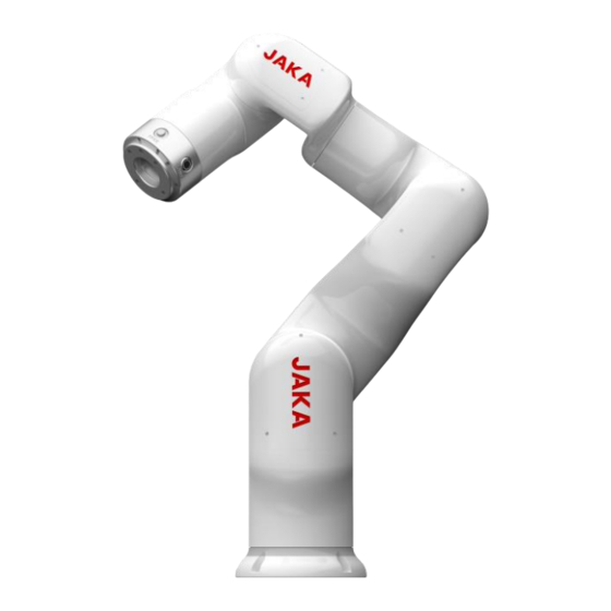
So, human-machine collaboration is easier. And the working efficiency is improved greatly. JAKA MiniCobo is a small six-axis collaborative robot, with a payload of 1Kg. It is a collaborative robot developed by JAKA, which is aimed at commercial application scenarios. -
Page 7: Product List
Product List When you purchase a whole set of JAKA MiniCobo robot, the package list you receive is as follows: Name Quantity JAKA MiniCobo Robot JAKA MiniCab Controller and control handle 24VDC power adapter Power cord and connecting cable JAKA certificate... -
Page 8: Chapter 1 Safety Specification
Chapter 1 Safety Specification 1.1 Introduction This chapter mainly introduces the safety principles and specifications that shall be obeyed when using robots and robot systems. Users shall carefully read the safety related contents in this manual and strictly obey them. Operators shall be fully aware of the complexity and danger of the robot system and pay special attention to the contents related to warning signs. - Page 9 3. Do not switch on/off the power supply system frequently. 4. When the robot load exceeds the set range, it will stop moving to prevent damage to the robot and injury to the operator. Because JAKA robot controller has the collision detection function. If the operator uses his own controller or active closes the protection function, he has to bear his own risk.
-
Page 10: General Warnings And Reminders
All safety information contained in this manual shall not be regarded as a guarantee of JAKA. Even if all safety instructions are complied with, injury or damage, which caused by an operator, may occure. -
Page 11: Use Purpose
JAKA MiniCobo collaborative robots are mainly aimed at commercial application scenarios, especially suitable for commercial or light industry, such as new retail, education, 3C manufacturing, processing of light parts, loading and unloading, etc. JAKA MiniCobo is only allowed to be used under specified conditions and environments. - Page 12 Note: 1. Make sure that your back or other parts of your body are not overloaded when you lift the device. Use appropriate hoisting equipment. JAKA is not responsible for the personal injury caused during the transportation of the equipment.
-
Page 13: Chapter 2 Welcome To Use Jaka Minicobo
(end-effector side), there are buttons for dragging and programming, and a TIO interface for connecting tools. (2) Controller and Operation Handle: They are the control system of the robot. JAKA's robot controller is equipped with a user-friendly handle to control the robot's operation and emergency stop. -
Page 14: Robot Body
Figure 2-2 MiniCobo collaborative Robot Body 2.3.1 Robot Indicator Lights JAKA MiniCobo commercial collaborative robot is equipped with indicator lights on the base of it. -
Page 15: End Tool Flange Button And Interface
2.3.2 End tool flange button and interface JAKA MiniCobo commercial collaborative robot is equipped with a tool IO interface and two buttons on the side of the end tool flange. The buttons are a drag button (FREE) and a record point button (POINT), as shown in the figure 2-3. -
Page 16: Controller And Its Handle
2.4 Controller and its handle The controller of JAKA MiniCobo commercial collaborative robot contains various electrical interfaces. For detailed information, please refer to Chapter 4 "Electrical Interface". The controller provides a control handle. The operator can start the robot only through the control handle without using APP, after writing and setting the default loading operation program. - Page 17 When power is on, press any button, and the handle buzzes twice a second. During the power-on process, JAKA LOGO lamp on the handle flashes red, blue and green alternately in breathing light, accompanied by three buzzes. Then JAKA LOGO lamp turns orange and waits for the IPC (Industrial Computer) to go online.
-
Page 18: Chapter 3 Mechanical Specification
3.1 Robot Workspace 3.1.1 Overall Dimensions of robot The practicality picture and overall dimensions of JAKA MiniCobo robot and MiniCab controller are shown in Figure 3-2 and Figure 3-3. Range of motion of the robot must be taken into consideration during installation, so as not to injure circumjacent personnel and equipment. -
Page 19: Robot Workspace
Figure 3-3 Overall Dimensions of JAKA MiniCobo and Minicab controllers 3.1.2 Robot Workspace The working space of JAKA MiniCobo robot is shown in Figure 3-4. When selecting installation position of the robot, accessible working region should be fully considered. Figure3-4 JAKA MiniCobo Workspace... -
Page 20: Installation
The robot should not be installed in a liquid or humid environment. 3.2.3 Robot Body Installation The JAKA MiniCobo robot can be installed in any posture. As is shown in Figure 3-5, there are three typical installation methods: normal-mounted, upside-down, and side-mounted. -
Page 21: End Tool Installation
3.2.4 End Tool Installation The end flange of the JAKA MiniCobo robot has four M6 screw holes, which can be used to fix end-effector in the robot. It is recommended to tighten the M6 screws during installation, with a torque of 15.3Nm. If you need fixing tools with high-precision, you can also use ∅6mm pin hole on the flange. -
Page 22: Technical Specifications
3.3 Technical Specifications 1.JAKA MiniCobo robot technical specifications Robot model: JAKA MiniCobo Payload 1.0kg Weight (including cable) 8.7kg Working radius 576.3mm Repeatability ±0.1mm Product Features Degree of freedom Graphical programming, drag-and-drop Programming programming (like Scratch programming) Teach pendant type Mobile terminal (PAD/mobile) APP Collaborative operation According to GB 11291.1-2011... - Page 23 3. 220V AC-DC power adapter Specification GST280A24-C6P Safety model GST280A64 DC voltage Rated current 11.67A Current range 0~11.67A Rated power (maximum) 280.08W Ripple and noise (maximum) 200mVp-p Voltage accuracy ±3% Linear regulation rate ±1% Load regulation rate ±3%...
-
Page 24: Chapter 4 Electric Parameters
Chapter 4 Electric Parameters 4.1 Introduction This chapter mainly describes the absolute limit parameters of MiniCab and the recommended operating conditions. When using the robot and MiniCab controller, users shall follow the recommended electric parameters. Reaching or exceeding the limit parameters may cause damage to the controller hardware. 4.2 Absolute Limit Parameter Table 4-1 Electric Limit Parameters Maximum... -
Page 25: Typical Power Consumption
So, when inputting the minimum voltage value, it is necessary to consider the abnormality caused by voltage loss and voltage sag. (3) The peak value of the output current is related to the adapted robot model and working status. (4) When the controller is working, its surface will be hot. So, it is necessary to use the controller in an environment with good ventilation and heat dissipation conditions. -
Page 26: Chapter 5 Definition Of Interface
Chapter 5 Definition of Interface MiniCab has user interfaces on the front panel and side panel. On the front panel, there are 20PIN integrated I/O interface, USB, HDMI, LAN, handle and E-STOP interface, Wi-Fi status indicator and On/Off button. On the side panel, there area power input interface, a robot body interface, 2.4G Wi-Fi antenna, and an internal integrated routing reset button. -
Page 27: Handle Interface (Stick)
The user integration I/O interface uses a double row of 3.5mm spacing pluggable terminal, which integrates rich interfaces for users. The specific interface pins are defined as follows: Table 5-2 Pin Definition of Integrated Interface Signal Name Signal Type Description Integrated interface 24V power output, with internal UDIO_24V integrated 2.7A overcurrent protection function... -
Page 28: Emergency Stop Interface (E-Stop)
System reservation Logic ground Note: (1) Only used to connect JAKA BP handle. External interface cannot be reformed arbitrarily. 5.1.3 Emergency Stop Interface (E-STOP) Figure 5-4 Diagram of E-STOP Interface The external E-STOP input interface uses double rows of 3.5mm spacing pluggable terminals. If this interface does not externally connect to emergency stop, the Pin1, Pin2, Pin3 and Pin4 shall be short-connected by wires. -
Page 29: Side-Panel Interface
2 and pin 3. To meet the requirement of current carrying capacity, it is recommended to use cable larger than 14AWG or 1.63mm 5.2.2 Robot Interface The COBOT port is the terminal of the robot body. Both terminals in it support the function of fool-proof with latch. JAKA provides adaptive cables for it. -
Page 30: Chapter 6 Minicab Detailed Introduction
6.2 Function Application This section is mainly to guide users to use JAKA MiniCab to control robot, so that the customers can use this controller more easily. At the same time, it involves the knowledge of robot operation. Please refer to user’s manual of the robot for detailed information. -
Page 31: Emergency Stop
2、The requirement of Power port P2 (logic power) is shown in the following table: Table 6-2 Description of Logic Power Requirements Rated Voltage 24VDC Voltage range 20~30VDC Typical power ≤30W Maximal power Note: 1) 20VDC for MiniCobo body is the under-voltage threshold value, excluding 20VDC. 2) This is only a recommended power supply model. - Page 32 Figure 6-4 Handle Control Box 1. Switch on and off via the user handle: Power-on: Short press the power button for 1s and then release. The buzzer rings and the controller is turned on. Shutdown: Long press the power button for more than 3s. The handle rings 6~7 times, and the controller is turned off.
-
Page 33: Led State Indicator
6.2.4 LED State Indicator JAKA collaborative robot is equipped with status indicators on the handle and panel. The color of the light is related to the status of the robot. The following is a comparison of LED lights and status indicated. -
Page 34: Integrated Udio
Table 6-3 LED Status Indicator Color Operating Status Blue Power-on but not enable Green Enable is OK Error Yellow Drag mode Yellow fast flashing Pause mode 6.2.5 Integrated UDIO The integration interface has 7 channels of IO, and each channel of UDIO_x has the function of NPN input and NPN output. -
Page 35: Braking Voltage Setting
and UDIO4, UDIO5 and UDIO6 can be combined into three I/O pairs to ensure that MiniCab can detect relevant signals in case of emergency. 6.3 Braking Voltage Setting The MiniCab has integrated voltage brake circuit to relieve the EMF(electromotive force) generated by the robot during deceleration and braking. -
Page 36: Wi-Fi
LAN2 port. And configure the LAN2 port IP address with the same network segment as the device used. If LAN2 network port is occupied, there is no other port to use except for LAN1 port, please contact JAKA technical service personnel to modify LAN1 network. - Page 37 1. Please do not set IP address network segment of the LAN2 port in the same segment as the one of LAN1 ports. Otherwise, it may cause login failure. 2. If LAN2 port must be set in 10.5.5.x network segment, please contact JAKA technical service personnel to modify the LAN1 network port.
-
Page 38: Chapter 7 Maintenance And Repair
All safety instructions in this manual shall be strictly followed during maintenance and repairing operation. Repairing operation shall be implemented by authorized system integrators or JAKA staff. The operation of replaced parts, which shall be returned to JAKA, should be in accordance with regulations in the service manual. -
Page 39: Maintenance Items And Cycles
As for maintenance items, please refer to the following table. In addition, overhauling shall be done after 20,000 hours of operation or every four years (the shorter period time prevails). If the maintenance and adjustment method is not clear, please contact JAKA Service Department. Cycle... -
Page 40: Replacement And Storage Of Parts
Examination Check/handlin Examination cycle Maintenance Check Items area g method Verificati on code Rout Every 3 Every year year year months year External Spatter, dust and Visual surface of other impurities inspection and controller attached cleaning Filter Whether or not Visual there is dirt or inspection,... -
Page 41: Cleaning And Replacement Of Parts And Components
Replacement operations shall be carried out by specific operators. Electric shock or accidental clamping by robot will result in serious injury or death. There are a large number of connection interfaces between PCB base plates. When replacing components, be cautious to avoid mis-connection or missing connection. -
Page 42: Commitment Of After-Sales Service
A-2:Regular replacement parts/recommended spare parts Maintenance parts-B: Maintenance parts prepared when purchasing several machines B-1:Parts purchased from JAKA In order to maintain normal operation, the above-mentioned A-1 and A-2 are the minimum essential parts required, and it is recommended to prepare a whole set of them. In addition, PCB board should use highly reliable components. - Page 43 After the expiry of the equipment warranty, our company will sign the relevant agreement with the user to determine the payment method, and guarantee to perform the follow-up service liabilities. III. After-sales service telephone number and contact information E-mail: Support.china@JAKA.com Telephone: 021-80392665 Information requested ...
-
Page 44: Chapter 8 Quality Assurance
The foregoing provisions do not imply a change in burden of proof, and do no profit loss to the user (customer). In the event of defective equipment, JAKA shall not be liable for any damage or loss resulting therefrom, including but not limited to production loss or damage to other production equipment. - Page 45 Shanghai JAKA Robotics Ltd. Address: Building 33-35, No.610 Jianchuan Rd, Minhang District, Shanghai Telephone: 400-006-2665 Website: www.jaka.com...
Need help?
Do you have a question about the MiniCobo V1 and is the answer not in the manual?
Questions and answers