
Related Manuals for SIGMATEK SR 020

Summary of Contents for SIGMATEK SR 020
- Page 1 SR 020 S-DIAS Current Controller Module Instruction Manual Date of creation: 12.09.2013 Version date: 26.07.2023 Article number: 20-029-020-E...
- Page 2 (print, photocopy, microfilm or in any other process) without express permission. We reserve the right to make changes in the content without notice. SIGMATEK GmbH & Co KG is not responsible for technical or printing errors in this handbook and assumes no responsibility for damages that occur through its...
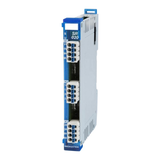
- Page 3 1 Power LED driver 1 LED driver The S-DIAS SR 020 current controller module is used to operate a DC motor with a 12-30 V supply voltage and a maximum motor current of 3.5 A. Higher starting currents are possible for a short period.
-
Page 4: Table Of Contents
SR 020 S-DIAS CURRENT CONTROLLER MODULE Contents Introduction ................5 Target Group/Purpose of this Operating Manual ...... 5 Important Reference Documentation ......... 5 Contents of Delivery ..............5 Basic Safety Directives ............6 Symbols Used ................6 Disclaimer ..................8 General Safety Directives ............ - Page 5 S-DIAS CURRENT CONTROLLER MODULE SR 020 Connector Layout ..............19 Status LEDs ................. 20 Applicable Connectors ............... 20 Label Field ................... 22 Wiring ..................23 Wiring Example ................23 Note ....................24 Assembly/Installation ............25 Check Contents of Delivery ............25 Mounting ..................
- Page 6 SR 020 S-DIAS CURRENT CONTROLLER MODULE 15.1.2 Servers ....................36 15.1.3 Communication Interfaces ..............38 15.2 Example ..................38 Documentation Changes ..............39 Page 4 26.07.2023...
-
Page 7: Introduction
General knowledge of automation technology is required. Further help and training information, as well as the appropriate accessories can be found on our website www.sigmatek-automation.com. Our support team is happily available to answer your questions. Please see our website for our hotline number and business hours. -
Page 8: Basic Safety Directives
SR 020 S-DIAS CURRENT CONTROLLER MODULE Basic Safety Directives Symbols Used The following symbols are used in the operator documentation for warning and danger messages, as well as informational notes: DANGER Danger indicates that death or serious injury will occur, if the speci- fied measures are not taken. - Page 9 S-DIAS CURRENT CONTROLLER MODULE SR 020 WARNING Hot Surfaces Surfaces chaudes INFORMATION Information Provides important information on the product, handling or relevant sections of the documentation, which require atten- tion. 26.07.2023 Page 7...
-
Page 10: Disclaimer
It does not guarantee properties under the warranty. Please thoroughly read the corresponding documents and this operat- ing manual before handling a product. SIGMATEK GmbH & Co KG is not liable for damages caused through, non-compliance with these instructions or applicable regulations. -
Page 11: General Safety Directives
S-DIAS CURRENT CONTROLLER MODULE SR 020 General Safety Directives The Safety Directives in the other sections of this operating manual must be observed. These instructions are visually emphasized by symbols. INFORMATION According to EU Directives, the operating manual is a component of a product. -
Page 12: Software/Training
SR 020 S-DIAS CURRENT CONTROLLER MODULE CAUTION Handle the device with care and do not drop or let fall. Prevent foreign bodies and fluids from entering the device. The device must not be opened! Manipulez l’appareil avec précaution et ne le laissez pas tomber. -
Page 13: Standards And Directives
The product was constructed in compliance with the following European Union directives and tested for conformity. 3.1.1 EU Conformity Declaration EU Declaration of Conformity The product SR 020 conforms to the following European directives: • 2014/35/EU Low-voltage Directive • 2014/30/EU Electromagnetic Compatibility (EMC Directive) •... -
Page 14: Type Plate
SR 020 S-DIAS CURRENT CONTROLLER MODULE Type Plate HW: Hardware version SW: Software version Page 12 26.07.2023... -
Page 15: Technical Data
S-DIAS CURRENT CONTROLLER MODULE SR 020 Technical Data Motor Output Specifications Number Supply voltage 12-30 V DC Controller frequency 30 kHz Current 0-3.5 A Motor peak start current Maximum I2T value = 16 A Operation mode S3 / 50 % with a maximum duty cycle of 1.5 min... -
Page 16: Current Output Specifications
SR 020 S-DIAS CURRENT CONTROLLER MODULE Current Output Specifications Number LED 1 0-20 mA at max. 10 V LED forward bias Resolution 8 bits LED 2 (power LED) 0-350 mA at max. 10 V LED forward bias Resolution 8 bits... - Page 17 S-DIAS CURRENT CONTROLLER MODULE SR 020 Current consumption on the S- typically 15 mA maximum 20 mA DIAS bus (+24 V supply) INFORMATION If this S-DIAS module is connected to an S-DIAS supply module with several S-DIAS modules, the total current of the modules used must be determined and checked.
- Page 18 SR 020 S-DIAS CURRENT CONTROLLER MODULE Page 16 26.07.2023...
-
Page 19: Miscellaneous
Shock resistance EN 60068-2-27 15 g Protection type EN 60529 IP20 INFORMATION The motor over temperature sensor is not provided with the drive. The products can only be used for the SIGMATEK S-DIAS listed in the file E247993. 26.07.2023 Page 17... -
Page 20: Mechanical Dimensions
SR 020 S-DIAS CURRENT CONTROLLER MODULE Mechanical Dimensions Page 18 26.07.2023... -
Page 21: Connector Layout
S-DIAS CURRENT CONTROLLER MODULE SR 020 Connector Layout INFORMATION The connections of the +24 V supply (X3: pin 1 and pin 2) or the GND supply (X3: pin 3 and pin 4) are internally bridged. To supply the mod- ule, only one connection to a +24 V pin (pin 1 or pin 2) and a GND pin (pin 3 or pin 4) is required. -
Page 22: Status Leds
SR 020 S-DIAS CURRENT CONTROLLER MODULE Status LEDs Module Status green module active no supply available BLINKING (5 no communication User yellow can be set from the application (e.g. the module LED can be set to blinking through the visualiza-... - Page 23 S-DIAS CURRENT CONTROLLER MODULE SR 020 26.07.2023 Page 21...
-
Page 24: Label Field
SR 020 S-DIAS CURRENT CONTROLLER MODULE Label Field Manufacturer Weidmüller Type MF 10/5 CABUR MC NE WS Article number Weidmüller 1854510000 Compatible printer Weidmüller Type Printjet Advanced 230V Article number Weidmüller 1,324,380,000 Page 22 26.07.2023... -
Page 25: Wiring
S-DIAS CURRENT CONTROLLER MODULE SR 020 Wiring Wiring Example 26.07.2023 Page 23... -
Page 26: Note
SR 020 S-DIAS CURRENT CONTROLLER MODULE Note The signals recorded by the analog modules are very small, as compared to the digital signals. To ensure error-free operation, a careful wiring method must be followed: • The DIN rail must have an adequate connection to mass. -
Page 27: Assembly/Installation
S-DIAS CURRENT CONTROLLER MODULE SR 020 Assembly/Installation Check Contents of Delivery Ensure that the contents of the delivery are complete and intact. See chapter Contents of Delivery. INFORMATION On receipt and before initial use, check the device for damage. If the device is damaged, contact our customer service and do not install the device in your system. -
Page 28: Mounting
SR 020 S-DIAS CURRENT CONTROLLER MODULE Mounting The S-DIAS modules are designed for installation into the control cabinet. To mount the modules, a DIN-rail is required. The DIN rail must establish a conductive connection with the back panel of the control cabinet. The individual S-DIAS modules are mounted on the DIN rail as a block and secured with latches. - Page 29 S-DIAS CURRENT CONTROLLER MODULE SR 020 Recommended minimum distances of the S-DIAS modules to the surrounding components or control cabinet wall: a, b, c … distances in mm (inches) 26.07.2023 Page 27...
-
Page 30: Addressing
SR 020 S-DIAS CURRENT CONTROLLER MODULE 10 Addressing Address Size Description (hex) (bytes) CFG for the Firmware (memory address range) 0200 0202 Data length Info (special purpose or status bits) 0204 Bit 0 PMB mode Bit 1 boot loader/ update request... - Page 31 S-DIAS CURRENT CONTROLLER MODULE SR 020 Address Size Access Type Description Reset point (hex) (bytes) Data sequence 1. 16-bit value Bit 10..0: Time / signal frequency Bit 11: 1 = use absolute time counter 0 = use relative time counter...
- Page 32 SR 020 S-DIAS CURRENT CONTROLLER MODULE Cyclic read 000A T the temperature in °K 0000 000C 16-bit actual value (sign) 0000 Status register latched (deleted when read, except bit 10 and 0000 bit 12) Bit 0 - reserved Bit 1: Wrong sequence (impermissible setting of output...
- Page 33 S-DIAS CURRENT CONTROLLER MODULE SR 020 Data sequence 3. 16-bit value Bit 10..0: Time / signal frequency Bit 11: 1 = use absolute time counter 0 = use relative time counter 0004 0000 Bit 12: left high Bit 13: right high...
- Page 34 SR 020 S-DIAS CURRENT CONTROLLER MODULE PWM distributor register for 20 mA LED 0018 Distributes the 50 MHz input signal in 5.55 MHz. 0009 5.55 MHz/256 (8-bit resolution) 20 kHz PWM frequency Distributor register for 350 mA LED 001A Distributes the 50 MHz input signal in 900 MHz.
-
Page 35: Transport/Storage
S-DIAS CURRENT CONTROLLER MODULE SR 020 11 Transport/Storage INFORMATION This device contains sensitive electronics. During transport and stor- age, high mechanical stress must therefore be avoided. For storage and transport, the same values for humidity and vibration as for operation must be maintained! Temperature and humidity fluctuations may occur during transport. -
Page 36: Maintenance
SR 020 S-DIAS CURRENT CONTROLLER MODULE 13 Maintenance INFORMATION During maintenance as well as servicing, observe the safety instruc- tions from chapter 2 Basic Safety Directives. 13.1 Service This product was constructed for low-maintenance operation. 13.2 Repair INFORMATION In the event of a defect/repair, send the device with a detailed error description to the address listed at the beginning of this document. -
Page 37: Sr020 Hardware Class
SR020 hardware class for the S-DIAS SR020 motor module This hardware class is used to control the SR 020 hardware module with 1 x DC motor driver, and 1 x 20 mA LED driver and 1 x 350 mA power LED drivers. More information on the hardware can be found in the module documentation. -
Page 38: Interfaces
SR 020 S-DIAS CURRENT CONTROLLER MODULE 15.1 Interfaces 15.1.1 Clients This client must be connected to an S-DIAS port, an "SdiasOut"_[x]” server. SdiasIn Place The physical location of the hardware module is entered in this client. Up to 64 modules, 0 to 63, can be assigned. - Page 39 S-DIAS CURRENT CONTROLLER MODULE SR 020 ErrorBits this server contains the status bits of the module. The respective bits mean the following: Bit 0... not defined Bit 1 .. no Sync available Bit 2... Flash Data CRC Error Bit 3...
-
Page 40: Communication Interfaces
SR 020 S-DIAS CURRENT CONTROLLER MODULE MotorCurrent This server shows the measured bridge current in mA. The relevant total current for the heating of the components both branches is measured. Higher values than the actual motor current are therefore shown in the component load range. -
Page 41: Documentation Changes
S-DIAS CURRENT CONTROLLER MODULE SR 020 Documentation Changes Change date Affected Chapter Note page(s) 04.10.2013 Note 23.10.2013 Addressing added Vibration resistance added 23.12.2013 3 Connector Layout Image changed 11.02.2014 3 Connector Layout Image changed 3.2 Applicable Connectors Connections added French notes added 4.1 Wiring Example... - Page 42 7 SR020 Hardware Class Chapter added 04.11.2020 5 Mounting Expansion functional ground connection 02.03.2021 7.1.1 Clients Client I2TThreshold updated 04.04.2022 1.4 Miscellaneous Variant SR 020-X added 06.12.2022 1.4 Miscellaneous UKCA conformity 26.07.2023 Document General chapters added, design Page 40 26.07.2023...
Need help?
Do you have a question about the SR 020 and is the answer not in the manual?
Questions and answers