Advertisement
Quick Links
Advertisement

Subscribe to Our Youtube Channel
Related Manuals for ROKAE NB220 Series


Summary of Contents for ROKAE NB220 Series
- Page 1 NB220 Series Product Manu al...
- Page 3 NB220 Series Product Manual Document No.:DOC-00001641 Version: A © Copyright 2015 ROKAE. All rights reserved.
- Page 4 Do not copy or reprint part or all of this manual without the consent of ROKAE. ROKAE has proofread the contents of this manual. However, the possibility of errors or inconsistencies cannot be ruled out, and ROKAE shall not be held liable for any errors or inconsistencies.
- Page 5 Content NB220 Series Product Manual...
- Page 6 NB220 Series Product Manual...
- Page 7 NB220 Series Product Manual...
- Page 9 For matters related to maintenance and repair of the robot, please contact our after-sales department or the local reseller. Service hotline: 400-010-8700. Get the following information ready when contacting us: ⚫ Controller model/serial number ⚫ Robot model/serial number ⚫ Software name/version ⚫ Problems with the system NB220 Series Product Manual...
- Page 11 2.1.1 Safety responsibility description ROKAE is dedicated to but not liable for providing reliable safety information. Even if all operations are carried out according to the safe operation instructions, we cannot guarantee that our industrial robots will not cause personal and property losses.
- Page 12 During the maintenance and repair of the equipment, a burn may be caused if the maintenance personnel touch the surface robot's hot surface. Electric The current operation may cause an electric shock with a shock serious or even fatal injury. NB220 Series Product Manual...
- Page 13 The robot system is designed in accordance with the following relevant standards: Standard Description 2006/42/EC Machinery directive 2014/30/EU Electromagnetic compatibility directive EN ISO 12100:2010 Safety of machinery - General principles for design - Risk assessment and risk reduction NB220 Series Product Manual...
- Page 14 Therefore, This emergency stop method provides the best protection for nearby equipment. Both safe stops arising from the opening of safety gate/safety grating in automatic mode and pressing of the emergency stop button in automatic mode are STOP 1. NB220 Series Product Manual...
- Page 15 Jog or run programs. Either releasing or pressing all the way down will cut off the motor power supply. NB220 Series Product Manual...
- Page 16 Therefore, one must observe the safety specifications when entering the working range of the robot. 2.3.1.2 About this section This section will describe some basic safety specifications to the end users of the robot. NB220 Series Product Manual...
- Page 17 2.3.3.3 Permission of using the Teach Pendant The mode selection switch of a standard Teach Pendant is equipped with a key, i.e. switchover between manual/auto modes is only possible using the key. Please keep the key properly and NB220 Series Product Manual...
- Page 18 2.3.4.3 Do not use the control cabinet for other purposes The control cabinet is only used to control motion of the robot arm body. Using it for any other purposes, such as standing on the cabinet body, working on the control cabinet and using the NB220 Series Product Manual...
- Page 19 During daily use of the robot, normal wear will occur to the band-type brakes of individual joints. It is very necessary to carry out band-type brake tests to ensure its functioning. The testing method is as follows: Operation NB220 Series Product Manual...
- Page 20 The motion velocity of the robot end is limited to less than 250mm/s in manual mode. This means that the maximum motion velocity of the robot end will not exceed 250mm/s whether you perform Jog or run programs on the robot, regardless of the set velocity in the program. NB220 Series Product Manual...
- Page 21 The fire-extinguishing equipment on the working site of the robot shall be supplied by the user. The user shall choose appropriate fire-extinguishing equipment according to the actual situations of the site. For fire with the controller, use a carbon dioxide (CO fire extinguisher. 2.3.12.2 Measures against severe fire NB220 Series Product Manual...
- Page 22 There are three types of personnel: ⚫ Operating personnel The operating personnel can switch on/off the robot power supply and start robot programs through the Teach Pendant or other interfaces, but may not enter into the safety zone. NB220 Series Product Manual...
- Page 23 The maintenance personnel should meet the criteria of operating personnel. In addition, the maintenance personnel should also have a certain level of other expertises (such as electrical, mechanical and pneumatic) and can complete their tasks according to manual documents. 2.4.3 Work content requirements NB220 Series Product Manual...
- Page 24 ⚫ Appropriate lighting should be provided during the maintenance. ⚫ In case of part replacement, make sure to use a part specified by ROKAE. Otherwise, the robot equipment may be damaged.
- Page 25 When the debugging is finished, execute a test run according to the following procedures: ⚫ At low velocity, execute the program one step after another for at least one cycle to confirm that everything is normal. NB220 Series Product Manual...
- Page 26 ⚫ When servicing the interior of the control cabinet, if it is necessary to touch the power supply unit or printed circuit board, make sure to switch off the power supply of the main circuit breaker of the control cabinet first to prevent electric shock. NB220 Series Product Manual...
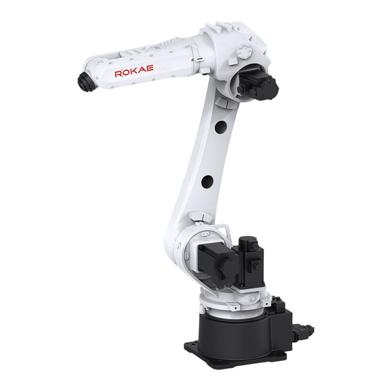
- Page 27 Fig. 2 Robot system Name Robot body Teach Pendant Teach Pendant cable Cabinet cable Controller 3.2.3 Robot arm body Among the NB220 series, each type of robot has 6 DOF. The number of DOF is equal to the NB220 Series Product Manual...
- Page 28 Base - The base is the foundation of the entire robot, with the electrical interface of the robot arranged behind it. Fig. 3 6-axis robot: Movement direction of each axis Component name Wrist Upper arm Lower arm Swing joint Base NB220 Series Product Manual...
- Page 29 Safety alert Do not enter into ! symbol the working area while the robot is on, since the robot may collide and cause severe accidents. NB220 Series Product Manual...
- Page 31 -65°~85° -65°~85° +156°~-99° -185°~80° -185°~80° +75°~-200° ±200° ±200° ±180° ±130° ±130° ±135° ±360° ±360° ±360° Maximum 120°/s 130°/s 130°/s velocity 110°/s 115°/s 115°/s 110°/s 120°/s 120°/s 150°/s 180°/s 180°/s 150°/s 180°/s 180°/s 220°/s 260°/s 260°/s NB220 Series Product Manual...
- Page 32 1300Nm 145kg.m2 Axis 5 1300Nm 145kg.m2 Axis 6 735Nm 85kg.m2 For NB220-170/2.7 models, the allowable moment and inertia are shown in the following table: Allowable torque Allowable inertia Axis 4 950Nm 89kg.m2 Axis 5 950Nm 89kg.m2 NB220 Series Product Manual...
- Page 33 The position of the center of gravity of the load is determined by the distance between the center of gravity and the flange surface. The distance is illustrated in the figure below. See the Load diagram for the rated distance. Fig. 6 Center of gravity of the load 4.4.3 Load diagram NB220 Series Product Manual...
- Page 34 4 Technical Specifications Fig. 7 Load diagram for NB220-220/2.7 Fig. 8 Load diagram for NB220-170/2.7 NB220 Series Product Manual...
- Page 35 The allowable inertia moment of NB220 series robots can be found in 4.4.1. Please calculate the inertia of the load before use and ensure that it is used within the allowable value.
- Page 36 4 Technical Specifications 4.5 Working space The NB220-220/2.7 working space is shown in the figure below: 1210 826±1 1115.12 756.79 1942.09 2705.46 Fig. 10 NB220-220/2.7 working space NB220 Series Product Manual...
- Page 37 4 Technical Specifications The NB220-170/2.7 working space is shown in the figure below: 1210 826±1 1115.12 756.79 1942.09 2705.46 Fig. 11 NB220-170/2.7 working space NB220 Series Product Manual...
- Page 38 4 Technical Specifications The NB220-150/3.2 working space is shown in the figure below: 826±1 1460 1450.46 800.18 2415.31 3201.16 Fig. 12 NB220-150/3.2 working space NB220 Series Product Manual...
- Page 39 To ensure the service life of the threads, do not remove the interface mounting screws frequently. The overall dimensions and external interface dimensions of NB220-220/2.7 are shown in the figure below: Fig. 13 Overall dimensions and mechanical interfaces of NB220-220/2.7 NB220 Series Product Manual...
- Page 40 4 Technical Specifications The overall dimensions and external interface dimensions of NB220-170/2.7 are shown in the figure below: Fig. 14 Overall dimensions and mechanical interfaces of NB220-170/2.7 NB220 Series Product Manual...
- Page 41 Pay attention to the interference zone at the end of the fixture during design. The mounting flange of NB220-220/2.7、NB220-170/2.7、NB220-150/3.2 robots is shown in the figure below: NB220 Series Product Manual...
- Page 42 4 Technical Specifications Fig. 16 Mounting flange NB220 Series Product Manual...
- Page 43 Connect the I/O signal cable and air pipe ① 5.3 Environmental conditions The robot is suitable for general industrial environments, which should meet the following conditions: Item Condition Temperature 0°C~+45°C Relative humidity 20%~80%, no condensation Electrical fast Below ±2kV transient (EFT) NB220 Series Product Manual...
- Page 44 Unpacking procedures: ① Step 1: Open the wooden packaging box Put on a pair of protective gloves, remove the fixed bolts, and move the wooden box upwards to separate the wooden box from the bottom pallet. NB220 Series Product Manual...
- Page 45 Use a pair of scissors to cut off the sealing tapes of the cardboard box, open the cardboard box, and take out the Teach Pendant cable, the Teach Pendant and the robot cable under the Teach Pendant foam. Fig. 18 Unpacking the control cabinet and the Teach Pendant cardboard box NB220 Series Product Manual...
- Page 46 Handle the robot arm body carefully after removing the bolts. NB220 Series Product Manual...
- Page 47 Visually inspect the robot appearance for bumping and damage Ensure that the lifting device and equipment match the robot model Robots not installed directly should be stored according to "5.3 Environmental conditions" Make sure that the environmental conditions NB220 Series Product Manual...
- Page 48 Fig. 21 shows the contour size of the robot in the transportation posture, in which dimensions C and D indicate the center of gravity position of the robot for reference in transportation. Fig. 21 Reference handling dimensions of the NB220 series NB220 Series Product Manual...
- Page 49 In no case shall any person be allowed to stand below the place where the robot is being lifted. Warning Be sure to turn off all the power, hydraulic and air sources of the robot during the transportation. Fig. 22 Robot lifting and handling Component Lifting hook NB220 Series Product Manual...
- Page 50 Be careful not to tilt during the handling and transport slowly. Fig. 23 Handling the robot with forklift NB220 Series Product Manual...
- Page 51 ⚫ When removing any screws from the robot equipment, hold the robot steady in order to prevent rollover; Retrofitting or disassembling the equipment is prohibited. If disassembly is ⚫ necessary, please contact us. NB220 Series Product Manual...
- Page 52 Flat washer Mount the adaptation plate onto the foundation with four M20 chemical bolts (expansion bolts), then fix the robot base onto the adaptation plate with 8 socket head cap bolts M20×80. Tightening torque: 670±5 Nm. Warning NB220 Series Product Manual...
- Page 53 Therefore, the robot base must be able to bear this supporting reaction force. Name Description Fxy/N Force along any direction in the XY-plane Fz/N Force in the Z-plane Mxy/Nm Bending torque along any direction in the XY-plane Mz/Nm Bending torque in the Z-plane NB220 Series Product Manual...
- Page 54 Tips The above force and torque data are the limit values that may appear during the motion of the robot. The limit values occur seldom and cannot be reached at the same time. 5.6 Electrical connection NB220 Series Product Manual...
- Page 55 ⚫ Make sure that the equipment is properly grounded to avoid the risk of electric shock. 5.6.1 Definition of the robot arm body side ports NB220 Series Product Manual...
- Page 56 5 Environment and Installation Fig. 26 Definition of the robot arm body side ports Meaning Power port definition Signal port definition NB220 Series Product Manual...
- Page 57 DATA6+ BK1+ BK2+ RS485 BK3+ Band-type brake BK4+ BK5+ F-10 BK6+ 24V+ 24V Power supply 24V- 图 27 Power and signal 5.6.2 Definition of EE and AS pins Figure 28 Definition of EE and AS pins NB220 Series Product Manual...
- Page 58 Before wiring, power off the controller and related devices and place a warning symbol (e.g. do not turn on the power). Wiring when the power is on is extremely dangerous and may cause electric shock and/or failure of the robot system. NB220 Series Product Manual...
- Page 59 Heavy-duty connector 5.8 Brake release In order to facilitate debugging and maintenance, NB220 series robot has brake release buttons on the base. The operation steps are as follows: 1) Remove the 6-M3 screws on the brake release cover; 2) Open the brake release cover;...
- Page 60 Before the brake release of A2 and A3 joints, please use tools such as crane to fix the lower arm and forearm; otherwise, the arms will fall down due to the brake release, resulting in personal injury or equipment damage. NB220 Series Product Manual...
- Page 61 Then calibrate each axis (just click the corresponding calibration button on HMI to record the multiturn value of the encoder), which can ensure that the zero position after calibration is exactly the same as the first mechanical calibration. NB220 Series Product Manual...
- Page 62 Axis 6 zero point (please specify when ordering).It is recommended to design a 5(+0.02,+0.05)mm keyway on the end tool flange to cope with the calibration tool. Fig. 32 Calibration method Position Axis 1 calibration position Axis 2 calibration position Axis 3 calibration position NB220 Series Product Manual...
- Page 63 HMI and The joints with coupling relationship complete the calibration of that need to be calibrated simultaneously. joint. After this, you can continue to move the next joint. Repeat Step 3 until all robot joints are calibrated. NB220 Series Product Manual...
- Page 64 HMI, see Fig. 35). If the robot cannot return to the correct zero position, please contact us. Fig. 34 Zero position of the NB220 robot NB220 Series Product Manual...
- Page 65 6 Zero calibration Fig. 35 How to move to zero position NB220 Series Product Manual...
- Page 67 Other items can also be added according to the intervals. 1) With the power OFF Item Position Interval Daily months months months months Check screws Externally ● for loosening visible screws Screws ● around the NB220 Series Product Manual...
- Page 68 Check the whole Whole ● ● ● ● ● robot for abnormal robot sound and vibration Check for change in Whole ● positioning accuracy robot and deviation of the stop position from the start position NB220 Series Product Manual...
- Page 69 In addition, when using a manual pump, in order to ensure smooth removal of used oil inside the reducer, it is recommended that after a period of oil refill, stop for a period of time, wait until the outlet does not discharge any grease before continuing to refill oil. NB220 Series Product Manual...
- Page 70 The robot has been filled with a specified amount of grease when leaving the factory. Do not mix with other greases, otherwise, the reducer may break down after it is used for a period of time. 7.3.2.3 A1 Lubrication NB220 Series Product Manual...
- Page 71 6) Wipe the redundant grease out of oil outlet with a cloth, and install the plug at the oil outlet. Apply the Three Bond 1215 sealant to the screw thread of the plug. 7.3.2.4 A2 Lubrication Fig. 38 A2 grease refill NB220 Series Product Manual...
- Page 72 Three Bond 1215 sealant to the thread; 5) Before installing the plug at the oil outlet, run Axis 3 for 20min at the velocity NB220 Series Product Manual...
- Page 73 Be extremely careful when refilling the grease. Once grease gets into your eyes or mouth or adheres to your skin, refer to the following instructions: When grease gets into your eyes: Flush your eyes with running water and get NB220 Series Product Manual...
- Page 74 Oil outlet 7.3.3 Fastening of socket head cap screws Use socket head cap screws (hereinafter referred to as "screws", in Grade 12.9) at the positions requiring connection strength. When assembling, tighten the screws as per the NB220 Series Product Manual...
- Page 75 7.3.4.1 Safety risks with battery Under normal service conditions, the motor materials and liquid electrolyte in the battery will not be exposed to the outside as long as the battery remains intact. Only when the battery is NB220 Series Product Manual...
- Page 76 During the battery replacement, take necessary precautions to prevent others from switching on the system power supply. Step 2: Remove the fixing screws 6-M4X16 from the electrical installation board of the base and pull out the electrical installation board; NB220 Series Product Manual...
- Page 77 After replacement, conduct a zero calibration on the robot. If you have any problem during the adjustment, please contact ROKAE. Axes 5 and 6 of the robot are all driven by timing belts. If they become loosened, they may cause abnormal sound, accuracy decrease and other failures.
- Page 78 ⚫ Tighten the flange fixing screws (for the tightening torque, see 7.3.3); ⚫ Install the side cover of the upper arm. If the timing belt or sealing gasket is found to be damaged, replace it in time. After replacement, perform another zero calibration on the robot. NB220 Series Product Manual...
- Page 79 Again confirm that the robot is in the no-load, zero point attitude, and then take the emergency stop, can be directly power off if necessary, to ensure that the robot will not run accidentally when the pressure relief work. NB220 Series Product Manual...
- Page 80 Step 5: Repeat Step 4 until the valve core is completely loose Step 6: Remove the valve core and screw on the oil plug. Warning After removing the valve core, please keep the material properly. If it is lost, please NB220 Series Product Manual...
- Page 81 / power off state. Tool preparation: Prepare the pressure relief tools according to the table below Fig. 46 pressure relief tools NB220 Series Product Manual...
- Page 82 Warning Do not twist the wrong switch of Nitrogen bottle and the direction for tightening NB220 Series Product Manual...
- Page 83 Do not flush the robot with water; Do not clean the robot with compressed air; Do not clean the robot with chemical agent such as solvent and reagent; Do not clean the robot in case of incomplete robot appearance; NB220 Series Product Manual...
- Page 84 Position Code Remarks Reference section Timing 14040300106 B=9mm 7.3.5.1 belt 14040300105 B=9mm 7.3.5.2 Battery Base electrical 15020301005/15 Battery pack / 7.3.4 Encoder battery pack installation board 070401332 component Grease Wrist 19010100009 96 grease 7.3.2 (appropriate amount) NB220 Series Product Manual...
- Page 85 8.2 Analysis of the failure causes and countermeasures Possible failures of the robot are summarized in the table below. For those circumstances not mentioned in the list and for which causes cannot be identified, please contact ROKAE promptly. Failure...
- Page 86 May be caused by wear of oil seal lip by impurities in extreme conditions; May be caused by improper sealing NB220 Series Product Manual...
- Page 87 The offset may be caused by motor encoder failure. Position offset after The origin may be Perform the zero parameter changes lost due to calibration again. parameter changes. NB220 Series Product Manual...
- Page 89 Revision Revision Version Date Content 2023/11/26 Initial version NB220 Series Product Manual...
- Page 91 [Back cover page]...
Need help?
Do you have a question about the NB220 Series and is the answer not in the manual?
Questions and answers