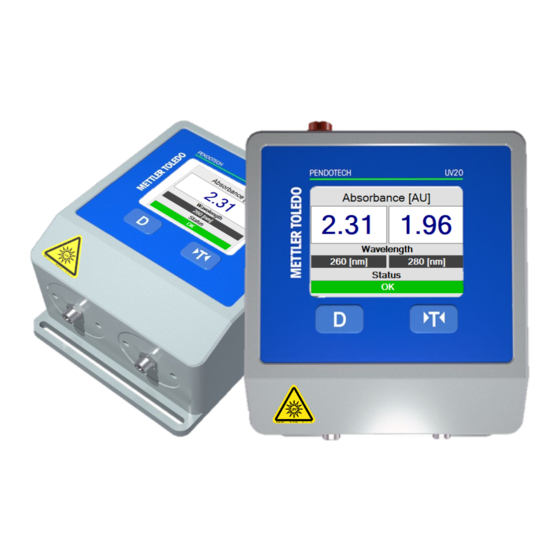
Summary of Contents for PendoTECH PM2
- Page 1 PENDOTECH® PM2 PHOTOMETER FOR UV/VIS ABSORBANCE AND TURBIDITY MEASUREMENTS USER’S MANUAL www.pendotech.com Tel: +1-609-799-2299 Copyright © 2022 PendoTECH...
-
Page 2: Safety Instructions
The PM2 Photometer must only be operated under Except for routine maintenance and cleaning procedures, the specified operating conditions. the PM2 Photometer must not be tampered with or altered in any manner. The PM2 Photometer should be installed and operated only by personnel familiar with the Maintenance and repair work must only be carried out by Photometer and who are qualified for such work. - Page 3 PendoTECH PM2 Photometer for UV Absorbance and Turbidity Measurements User’s Manual Revision 0 Optical Safety Warning: The photometer can emit light in the range Ensure that both ends of the fiber optic cables of 200 nm – 1100 nm. Hazardous UV and IR (photometer and flow cell connections) are properly radiation are emitted from the unit.
-
Page 4: Table Of Contents
PendoTECH PM2 Photometer for UV Absorbance and Turbidity Measurements User’s Manual Revision 0 Contents Safety Instructions .................................. 1 1 Disclaimer .................................... 4 2 Introduction and Unpacking ............................... 4 2.1 Identify the following components ..........................4 3 Flow Cell and Flow Cell Stand ............................. 5 3.1 Flow Cells .................................. -
Page 5: Disclaimer
The flow cells can be repeatedly cleaned and reused but are designed for single use. PendoTECH Flow Cell Stand is an accessory that can be used to house or mount these flow cells as an alternative to optical couplers. -
Page 6: Flow Cell And Flow Cell Stand
The flow cells contain a special silica glass window and compartments to insert optical couplers, which attach to the fiber optic cables from the photometer. The flow cells can also be used with PendoTECH’s Flow Cell Stand with integral couplers in place of the optical couplers to connect the fiber optic cables. -
Page 7: Unit Overview
PendoTECH PM2 Photometer for UV Absorbance and Turbidity Measurements User’s Manual Revision 0 4 Unit Overview Fig 2: PM2 (Photometer) dimensions in mm. 4-20 mA + RS485-A ZERO - 4-20 mA - RS485-B ALARM + 4-20 mA + ALARM -... -
Page 8: Hardware Installation
PendoTECH PM2 Photometer for UV Absorbance and Turbidity Measurements User’s Manual Revision 0 5 Hardware installation Please follow the outlined sections below as a guideline for installing the photometer and associated accessories. These guidelines apply for specific application installations or, in the case of OEM component installation onto a suitable panel. -
Page 9: Alarms
AU channels. The status textbox states “ALARM” and changes background to red. 5.4 Alarms Refer to the PM2 photometer’s Display, indicating an alarm condition. For the 4-20mA outputs will indicate alarms (going to high-level). Alarm Activator Cause Solution... -
Page 10: Configuration Of Unit For Laboratory Or Panel Mount Installations
5.5 Configuration of Unit for Laboratory or Panel Mount Installations PM2 has dual functionality to operate as a laboratory benchtop unit or panel mount unit. By default the configuration switch is in the L position or laboratory unit. In this configuration the power connector and the 8-pin circular input/output connector are active. -
Page 11: Electrical
NOTE: The fiber optic cables must be secured so they are not free to move around, be stepped on, leaned against, or otherwise damaged during normal operations. The minimum bend radius for fibers UV PM2 Photometer is 8” (20.3cm). Only hand tighten SMA-905 connections. Never use a wrench, pliers, or other tool. Over-... -
Page 12: Introduction To Absorbance Monitoring
Connect the power and ground to the system. For laboratory systems, a 24VDC power brick is included with every PM2. However, the global use wall plug(s) must be ordered separately. For panel-mounted systems, a 13-position terminal block connector is on the back of the PM2. Use a small flathead screwdriver to loosen the screw, insert a NON-ENGERGIZED 12-48VDC lead (with the end stripped so the metal wire is exposed) to position 9, and tighten the screw to secure the lead. -
Page 13: Led-Based Absorbance
The LED is located internal to the photometer and is specific to the application. Therefore, the PM2 UV photometer is a dedicated instrument for monitoring only one or two specific analytes of interest. Shown below are three example LED spectrum profiles graphs for typical LED light source wavelengths 260/280/300/880nm (Figures 5-8). -
Page 14: Glossary And Definitions
300nm LED 800nm LED Fig 8: LED wavelength spectrum example for 800nm UV PM2 Photometer. Fig 7: LED wavelength spectrum example for 300nm UV PM2 Photometer. In brief, the photometer works as follows: The measuring system is in the detector block of the photometer. Light is provided by an LED, which produces a stable light output at a narrow wavelength range. -
Page 15: Instrument Control
PendoTECH PM2 Photometer for UV Absorbance and Turbidity Measurements User’s Manual Revision 0 8 Instrument Control 8.1 Zero 4-20 mA + RS485-A ZERO - 4-20 mA - RS485-B ALARM + 4-20 mA + ALARM - 4-20 mA - 12-48 VDC... -
Page 16: System Specification
10.3 Service Information Any product which is under warranty must be returned to PendoTECH for repair. If out of warranty, the user should call PendoTECH for over-the-phone assistance and our service staff will help determine if the unit should be returned for repair.


Need help?
Do you have a question about the PM2 and is the answer not in the manual?
Questions and answers