Advertisement
Quick Links
Advertisement

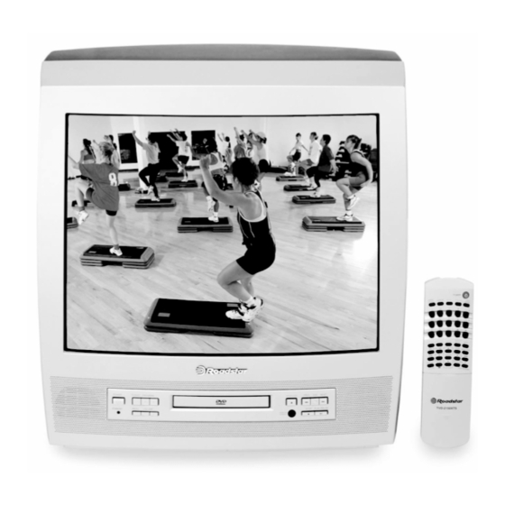
Summary of Contents for Roadstar TVD-2150
- Page 1 TVD-2150...
- Page 3 SERVICE MANUAL 14" TV+DVD SOLID STATE Color Television Receiver (TV SECTION) PAL SECAM VERSION TOSHIBA I C IC GREAT WALL DIGITAL TV RESEARCH INSTITUTE This manual is the latest at the time of printing, and does not include the modification which may be made after the printing, by the constant improvment of product.
- Page 4 CONTENTS ( TV SECTION ) 1. SPECIFICATION........2. BLOCK DIAGRAM........3. ALIGMENT INSTRUCTION....... 4. VOLTAGE TABLE........5. IC601 DATA........... 6. BLOCK DIAGRAM........7. WIRING DIAGRAM......... This manual is the latest at the time of Printing , and does not include the modification Which may be made ofter the Printing, by the Constant improvement of Product.
- Page 5 MODEL : 14" ITEMS OF MEASUREMENT STANDARD UNIT < 57 dbuv VIDEO SENS. AT S/N 30db L - VHF H - VHF < 57 dbuv < 60 dbuv < 42 dbuv SOUND SENS. AT S/N 30db L - VHF < 42 dbuv H - VHF <...
- Page 6 SM -49PM P.3...
- Page 7 ALIGNMENT INSTRUCTION I.PLEASE READ BEFORE ATTEMPTING SERVICE 1.Do not connect any antenna plug directly to the tuner socket and do not connect any equipments directly to the TV chassis,otherwise it may be burnt out the TV or equipment,execept an isolation transformer is used for main power source or the TV sets.
-
Page 8: Vertical Center Adjustment
VI.VERTICAL S-CORRECTION ADJUSTMENT 1. Receive Cross hatch Pattern 2. Select VSC item adjust value to normal,regular picture. VERTICAL CENTER ADJUSTMENT 1. PAL (50Hz) Adjustment (1). Receive Monscope Pattern (50Hz). (2). Select VP50 item adjust value to obtain the picture at center . 2. - Page 9 VIII. WHITE BALANCE ALIGNMENT STEP (Deqauss the picture by deqaussing coil if necessary) 1. Disconnect the any input signal,set the blue black OFF. 2. Enter to D MODE. 3. Adjust the RCUT,GCUT,BCUT value to 80,GDRV,BDRV to 45,BRTS to CO. 4. Adjust the BRIGHT,CONT to min. 5.
-
Page 10: Hotel Lock Setting
HOTEL LOCK SETTING 1.Adjust the volume to the lowest level “00”. 2.Press “Vol-” button on the front panel of the set and “Mute “button on the remote control at the same time ,the set will switch to Hotel Mode,and the menu as shown below will appear on the screen. - Page 11 ENTER D-MODE SETTING 1.Adjust the volume to the lowest level “00”. 2.Press “Vol-” button on the front panel of the set and “display “button on the remote control at the same time ,the set will into D-Mode mode,and the DATA will appear on the screen.
- Page 12 For 14 VOLTAGE TABLE FOR TRANSISTOR (ONLY FOR REFERENCE) C (V) E (V) SYMBOL E (V) SYMBOL C (V) B (V) B (V) Q507 Q101 Q508 Q102 Q601 Q103 Q603 Q104 Q604 Q105 Q605 Q106 Q606 Q201 17.2 17.5 -0.8 Q801 Q202 22.8...
- Page 13 SYMBOL ITEM(FOR PAL) FOR NTSC PRESET DATA(14") REMARK ROUT ROUT R CUTOFF GOUT GOUT G CUTOFF BOUT BOUT B CUTOFF GDRV GDRV G DRIVE BDRV BDRV B DRIVE CNTX CNTX SUB CONTRAST MAX BRTC BRTC SUB BRIGHT CENTER COLC COLC SUB COLOR CENTER For NTSC TNTC TNTC...
- Page 14 SECAM B-Y SECAM R-Y RAGC RAGC RF AGC Adjustment PIF VCO Adjuetment HAFC 1/2 AFC data adjustment Volume output data at 25% Volume output data at 50% BRTS SUB Brightness (DIFFERENCE) Bit 7: Scart input level, 0: high, 1: low , Bit6: Pow er on state, O: Last memory, 1: standby MOD 0 MOD 0...
- Page 15 TABLE 1 Option item selection (MOD 0) Color Mode Selection Bit 7 0: Auto,PAL,NTSC3.58,NTSC4.43, 1: Auto,PAL,NTSC3.58/4.43,PAL-M/N Color Mode Selection Bit 6 0: No use, 1: SECAM Bit 5 0: CVBS input, 1: Y/C input (TV+DVD Chassis action) Bit 4 Teletext Selection 0: No use, 1: Teletext action Bit 3 Stereo Selection...
- Page 16 Table 6 Language selection Bit 0 1: Portugal Bit 1 1: Hungrian Bit 2 1: Nederland ID SW(ID Sensitivity Sw itching 0: Normal 1: Low Mode(This function w orks on only for NTSC Mode) No use ABL-Gain 00: -0.74V, 01: -0.64V 10: -0.37V, 11: -0.12V ABL Start Point 00: -0.01V, 01: -0.11V...
- Page 17 VOLTAGE TABLE FOR IC ( ONLY FOR REFERENCES ) ( FOR 1P.TEXT ) IC302 SYMBOL IC101 IC601 IC401 TDA5348 IC801 IC802 PIN NO. (SECAM) (TB1238) (CPU) 2.6 2.9 5.0 5 5 0.6 12.7 12.9 3.6 3.6 4.7 2.3 2 GND 2.5 2.6 24.4 24.4 8.6 8.9...
- Page 18 VOLTAGE TABLE FOR IC ( ONLY FOR REFERENCES ) ( FOR 1P.TEXT ) SYMBOL IC402 IC103 IC001 IC602 IC102 PIN NO. 12.2 11.9 9 8.8 5 4.9 5 4.9 5 4.9 0.05 0.05 0.05 12.2 NOTE : VOLTAGE ARE TAKEN UNDER TUNED CONDITION WITH CONTRAST Maximum Position BRIGHTNESS...
- Page 19 VOLTAGE TABLE FOR IC ( ONLY FOR REFERENCES ) ( FOR 1P.TEXT ) SYMBOL IC901 IC903 IC905 PIN NO. 3.28 15.1 5.01 NOTE : VOLTAGE ARE TAKEN UNDER TUNED CONDITION WITH CONTRAST Maximum Position BRIGHTNESS Maximum Position COLOR Maximum Position SIGNAL INPUT 70dB +10dB CHANNEL SETTING...
- Page 20 SM-49PM.17...
- Page 21 SM-49PM P.18...
- Page 23 ROADSTAR MANAGEMENT SA. (INTERNATIONAL SERVICE DIVISION) Via Passeggiata, 1 - BALERNA - SWITZERLAND Tel. +4191-6975155 - Fax. +4191-6975151 e-mail: aftersal@roadstar.com ROADSTAR ITALIA S.P.A. SERVICE DIVISION (DOMESTIC ITALY) Viale Matteotti, 22 - CERNOBBIO (CO) -ITALY Tel. +39031-342340 - Fax. +39031-3346291...


Need help?
Do you have a question about the TVD-2150 and is the answer not in the manual?
Questions and answers