Table of Contents
Advertisement
Quick Links
Advertisement
Table of Contents

Related Manuals for enertik BC-F20HWR2-200L

Summary of Contents for enertik BC-F20HWR2-200L
- Page 1 All in one type heat pump water heater Installation and user manual...
- Page 2 -- 1 --...
-
Page 3: Table Of Contents
Content 1. Safety information .................. 2 2. Preparations of installation ..............3 3. Installations .................... 6 4. Trial-running ..................11 5. Unit parameters ................... 12 6. Operation ....................13 7. Troubleshooting ................... 15 8. Maintenance ..................17 9. Wi-Fi Function ..................18 9.1 Software installation .............. - Page 4 The heat pump unit is required reliable earthing connection before usage;otherwise WARNING it might cause death or injury. If you cannot confirm that your house power supply is earthed well,please do not install the unit before carefully check it. Please have a qualified person to check the reliable earthing connection and install the unit. Examples of a qualified person include:Licensed plumbers,Authorized electric company personnel,and Authorized service personnel.
-
Page 5: Safety Information
1. Safety information Please carefully read thoroughly all of the instructions before installing or operating the unit. Following safety symbols are very important,please carefully read and always obey all safety symbols. It maybe cause that people is injured if not obey the instructions. CAUTION It maybe cause that people is seriously injured or killed if not obey the WARNING... -
Page 6: Preparations Of Installation
Before cleaning,be sure to stop the operation and turn the breaker off or pull out the power supply plug.Otherwise, an electric shock and injury may be caused. Produced hot water temperature can reach over 50℃. It can cause severe burns instantly or death form scalds. Children,disabled and elderly persons are at highest risk of being scalded.Feel water is necessary before bathing or showering.So,water temperature limiting valves are recommended. - Page 7 2.3 Installation site requirements Enough space for the unit installation and maintenance should be preserved. The surrounding of air inlet and outlet should be free from obstacles and strong wind. The base surface should be flat,surface should be inclined no more than 2° and able to bear the weight of the unit and suitable for installing the unit without increasing noise or vibration.
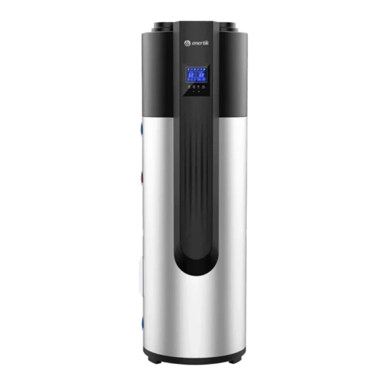
- Page 8 2.5m height ceiling and with 3m length by 2m width. 2.5 Unit dimension F L ON OF S E T T IM E R M O D E O N /O F F LOCK Model BC-F20HWR2-200L BC-F25HWR2-250L BC-F25HWR2-300L Parameter Diameter D(mm) High H(mm) 1802...
-
Page 9: Installations
3. Installations The circulating air flow of every unit should be more than 450m³/h.Please make sure that there is enough installation space. 3.1 Water system piping diagram Power supply User Notes: The PTR valve is only Water leaving available for some models. The temperature limiting valve PTR valve (1) Temp.limiting... - Page 10 After water system piping work,turn on the cold water inlet valve and hot water outlet valve and start effusing the tank.When water flow smoothly out from tap of water outlet,it means the tank is full.Please turn off all valves and check pipeline to make sure there is without any leakage.
- Page 11 The duct specifications: Duct type Rectangle duct Round duct Dimensions 177mmx77mm Φ177mm Straight ≤2Pa/m ≤2Pa/m Pressure drop Bent ≤2Pa/m ≤2Pa/m Bent quantity ≤3 ≤3 NOTES When the air duct is connected, the unit capacity will be decreased because of the decreased air flow by the resistance of the duct.
- Page 12 3.4 Electric connection CAUTION The power supply should be an independent circuit with rated voltage. Power supply circuit should be earthed effectively. The wiring must be performed by professional technicians in according with nation wiring regulations and the unit circuit diagram. An all-pole disconnection device which has at least 3mm separation distance in all poles and a residual current device (RCD)with the rating of above 10mA shall be incorporated in the fixed wiring according to the national rules.
- Page 13 3.5 Installation checking 3.5.1 Location checking The flooring beneath the water heater must be able to support the weight of the unit when filled with water. Located indoors (such as a basement or garage) and in a vertical position. Sheltered from the freezing temperatures.
-
Page 14: Trial-Running
4. Trial-running 4.1 Water perfusion before operation If the unit is used for the first time or used again after emptying the water tank,please make sure that the tank is full of water before turning on the power. Method:please refer to the figure. When water flows out from the hot Open the cold water inlet valve water outlet,the tank is full.Turn... -
Page 15: Unit Parameters
5. Unit parameters Model: BC-F20HWR2-200L BC-F25HWR2-250L BC-F25HWR2-300L *Test Condition:Ambient Temperature: (DB/WB) 20°C / 15°C;Water Temperature from 15°C to 55°C Rated Heating Capacity(kW) 1.80 2.42 2.42 Rated input power(kW) 0.47 0.62 0.62 3.82 3.88 3.88 Hot Water Volume(L/h) 39.00 52.00 52.00 Operation Range(℃)... -
Page 16: Operation
6. Operation 6.1 Controller panel explanation 6.2 Explanation of icons Sign Name Sign Name ERROR sign BATH sign STANDBY TIMING key CYCLIC VENTILATION sign LOCK sign ELECTRIC HEATER sign DEFROSTING sign HEATING sign 6.3 Explanation of buttons After the unit is powered on,the display screen will display all the icons for 3 seconds,and it will be display the regular interface automatically. - Page 17 6.4 Operation guidance table Item Operation Method Touch both the UP key and the DOWN key for 5s to unlock.when unlocking, the Unlock LOCK sign is off.when locking, the LOCK sign is on. Touch the ON/OFF key, the unit will turn off if the panel is on and turn on if the panel ON/OFF is off.
-
Page 18: Troubleshooting
7. Troubleshooting 7.1 Non-error tips Q: Why compressor cannot start immediately after setting? A: Unit will wait for 3 minutes to balance the pressure of the refrigerant system before starting compressor again.It is a self protection logic of the unit. Q: Why sometimes the temperature shown on the display decreased while unit is running?... - Page 19 Code Description Corrective action Maybe:the connection is not well. Coil temperature sensor error Maybe:the sensor is broken. Maybe:the PCB is broken. Maybe:the connection is not well. Suction temperature Maybe:the sensor is broken. sensor error Maybe:the PCB is broken. Maybe:the connection is not well. Outdoor ambient Maybe:the sensor is broken.
-
Page 20: Maintenance
NOTE The diagnostic codes listed above are the most common.If a diagnostic code not listed above is displayed,please contact residential technical assistance. If any of E01/E02/E04 continuously appear 3 times within 30 minutes,the unit will consider it as heat pump system error,and the unit will stop running.The unit will run until the power supply is reset. -
Page 21: Wi-Fi Function
Wi-Fi Function 9.1 Software installation ① Method 1: Search “Smart life” in your APP store ,install “ ”.Click “GET” to install. ② Method 2: Scan the QR code below. 9.2 Software registration and configuration 9.2.1 Registration ① Users don’t have account can click “Register” to create an account: Register Enter your phone number Get Verification Code Enter Verification Code... - Page 22 ② After registration, you need to Create a Home:Create a Home Set Home Name Set Home Location Add Rooms. 9.2.2 Account id+ password login ① Existing accounts can be logged in directly, in the following order.
- Page 23 ② If you forget your password you can choose to login with your verification code and select "Forget Password": Enter your phone number Get verification code . ③After creating a home or logged in,enter the main interface of APP.
-
Page 24: Wi-Fi Module Configuration Steps
Note: Click “+” or “Add Device” to add devices. Click the device to check the status, and you can set the operating mode, ON/OFF, timer. 9.2.3 Wi-Fi module configuration steps Method 1 Step 1: EZ Mode: When power is on, press and hold the keys at the same time for 3 seconds to enter the distribution network. - Page 25 Step 3: Open the "smart life" APP, log in into the main interface, click on the top right corner "+" or "add equipment" of the interface, enter the equipment type selection, the "Large Home Appliances", select "Smart Heat Pump" equipment and add equipment into the interface.
- Page 26 Method 2 Step 1 AP Mode: Press and hold the keys at the same time for 3s to enter the distribution network. The " " icon will flash slowly. Step 2&3 Same with EZ Mode above. Step 4 After entering the add device interface, click "EZ Mode" in the upper right corner; Enter the AP mode to add the device interface, confirm that the AP mode has been selected, and click"Confirm indicator slowly blink".
- Page 27 Enter the mobile phone Wi-Fi connection interface, find the “Smart Life_XXXX” connection, and the APP will automatically enter the device connection status. Step 5 : Same as EZ mode above. Note: If the connection is failed, please enter the AP mode manually and reconnect according to the above steps. 9.2.4 Software function operation After the device is bound successfully, enter the operation interface of “Smart heat pump”...
- Page 28 After the device is bound successfully, enter the operation interface of “Smart heat pump” (Device name, modifiable) In the main interface of “Smart Life”, click “Smart heat pump” to enter the operation interface. ①Back ②More: You can change device name, select device installation location, check networking status, add shared users, create device cluster, view device information, and more.
- Page 29 Device sharing To share a bound device, the user should do so in the following order. After successful sharing, the list will be added to show the person shared If you want to delete the account you shared to, cross the selected account to the left,and delete it. The user interface is as follows.
-
Page 30: Device Removal
The interface of the person to be shared is as follows. The received shared device is displayed. Click it to operate and control the device. 9.2.5 Device Removal By wire controller Long press for 3s to enter EZ mode, it returns to connection state and flashes rapidly again. - Page 31 By APP Click “ ” on the top right corner of the main interface to enter the device details interface, and click “device removal” to enter EZ mode. The network can be reconfigured within 3 minutes, it will exit if no connection operation in 3 min. The specific operations are shown as follows.
Need help?
Do you have a question about the BC-F20HWR2-200L and is the answer not in the manual?
Questions and answers