
Related Manuals for Pewatron MEAN WELL TN-3000


Summary of Contents for Pewatron MEAN WELL TN-3000
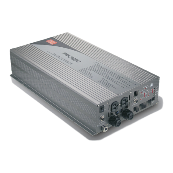
- Page 1 040-07-409-021-EH-0413.pdf 040-07-409-021-EH-0413 TN/TS-3000 Inverter Instruction Manual...
-
Page 2: Table Of Contents
040-07-409-021-EH-0413.pdf 040-07-409-021-EH-0413 TN/TS-3000 Inverter Instruction Manual Index 1. Safety Guidelines ................2. Introduction ....................................2 .1 Features ................ 2.2 Main Specification 2.3 System Block Diagram ..............3. User Interface Panel ................................3.1 Front Panel ............3.2 AC Terminal Configuration ............ -
Page 3: Safety Guidelines
040-07-409-021-EH-0413.pdf 040-07-409-021-EH-0413 1.Safety Guidelines (Please read through this manual before assembling the inverter) Risk of electrical shock and energy hazard. All failures should be examined by a qualified technician. Please do not remove the case of the inverter by yourself! After connecting the AC input of the inverter to the utility, the AC outlet of the inverter will have AC output even if the power switch on the front panel is in the OFF position. -
Page 4: Features
040-07-409-021-EH-0413.pdf 040-07-409-021-EH-0413 TN-3000 is equipped with 2 methods of battery charging. An AC charger and solar charger coexist in this unit. The user only needs to connect their own battery banks and solar panel to form an energy saving independent power station which is in line with our goals of conserving energy and being environmental friendly. -
Page 5: Main Specification
040-07-409-021-EH-0413.pdf 040-07-409-021-EH-0413 2.2 Main Specifications TN/TS-3000 MODEL 3000W continuously, 3450W for 3 minutes, 4500W for 10 seconds, 6000W Rated power for 30 AC cycles Factory 110V 60Hz 230V 50Hz setting Output voltage 200 / 220 / 230 / 240V (adjustable) 100 / 110 / 115 / 120V (adjustable) Frequency 50 / 60Hz 0.1Hz... - Page 6 040-07-409-021-EH-0413.pdf 040-07-409-021-EH-0413 Receptacle type TYPE-A TYPE-B TYPE-C TYPE-D TYPE-E TYPE-F Country EUROPE AUSTRALIA JAPAN GFCI Certificate (Expect for 48V input) No fuse breaker with reset button (for AC input): Under "bypass mode", when the AC output is shorted or the load current exceeds the rated current of the No Fuse Breaker, the Breaker will open and that stops bypassing energy for the utility thus prevent possible danger.
-
Page 7: Ac Terminal Configuration
040-07-409-021-EH-0413.pdf 040-07-409-021-EH-0413 3.2 AC Terminal Configuration When the load current is >15A, you must use this output terminal connection (terminal can withstand 3000W). To ensure user safety, please follow the wiring instructions as below: This AC terminal block can be found inside the inverter. To access it, the front panel must first be removed then the output wires can be screwed onto the AC output terminal block. -
Page 8: Rear Panel
040-07-409-021-EH-0413.pdf 040-07-409-021-EH-0413 BATTERY indicator: Display the remaining capacity of external batteries. LOAD indicator: Display the output load level. 3.5 Rear Panel Battery input (+),(-). Solar panel input connector. Fan ventilation openings. Reverse Polarity Will Damage The Unit. Figure 3.2 Rear panel (TN-3000) 4.Explanation of Operating Logic TN-3000 is CPU digital controlled true sine wave DC/AC inverter. -
Page 9: Explanation Of Ups Mode Control Logic
040-07-409-021-EH-0413.pdf 040-07-409-021-EH-0413 4.1 Explanation of UPS Mode Control Logic Utility Power Power-On Re-power-on By pass mode Inverter Mode 28.5V 28.5V 28.5V 28.5V 25.4V 26.5V 22.5V 26.5V 26.5V (Alarm) Battery voltage 21V(Shut-down) 29.0V Solar charger state AC charger state t9 t10 t11 Figure 4.1 Diagram of UPS mode control logic t1: To ensure the battery is at full capacity, when the TN-3000 is turned ON, the CPU will execute the "bypass mode"... - Page 10 040-07-409-021-EH-0413.pdf 040-07-409-021-EH-0413 time or cloudy day) taking over battery charging duty and at this time the solar charger indicator will turn OFF. t4 : With the charger activated, voltage of the battery bank will increase gradually until 28.5V is reached then the CPU will shut off the charger to prevent over charging.
-
Page 11: Explanation Of Energy Saving Mode Control Logic
040-07-409-021-EH-0413.pdf 040-07-409-021-EH-0413 4.2 Explanation of Energy Saving Mode Control Logic Utility Power Power-On Bypass mode Inverter Mode 28.5V 28.5V 28.5V 28.5V 26.5V 22.5V 26.5V 26.5V 22.5V (Alarm) Battery (Alarm) voltage 21.0V (Shut-down) Solar charger state AC charger state t6 t7 Figure 4.2 Diagram of energy saving mode control logic t1 : To ensure the battery is at full capacity, when the TN-3000 is turned ON, the CPU will execute the "bypass mode"... -
Page 12: Tn/Ts-3000 Initial Output Voltage & Frequency And Procedure To Setting Operating Mode
040-07-409-021-EH-0413.pdf 040-07-409-021-EH-0413 t5 : When the capacity of batteries goes down to battery voltage around 26.5V, solar charger will restart and begin charging. t6 : If the energy provided by the solar panels is lower than consumed by the loads, voltage of the battery bank will decrease gradually to battery voltage around 22.5V. -
Page 13: Initial Setting For Transition Voltages
040-07-409-021-EH-0413.pdf 040-07-409-021-EH-0413 5.2 Initial Setting for Transition Voltages TN/TS-3000 Factory Setting AC charger 14.3V 28.5V transition voltage AC charger start up voltage Solar charger 13.3V 26.5V start up voltage Solar charger 14.3V 28.5V shutdown voltage Inverter 10.5V shutdown 5.3 Procedures to Setting Operating Mode, Output Voltage, Frequency, and Standby Saving Mode AC Receptacle SOLAR CHARGE... - Page 14 040-07-409-021-EH-0413.pdf 040-07-409-021-EH-0413 (Factory setting: UPS mode) Energy saving Bat Low mode Light Saving Dark Flashing UPS mode Bat Low Saving Table 5.1 LED indication for operating mode Step 4 The LEDs will change state from pressing the setting button for 1 second and then release.
-
Page 15: Remote Monitoring Software (Optional Accessory)
040-07-409-021-EH-0413.pdf 040-07-409-021-EH-0413 Procedure 3 involves standby saving mode selection, the steps are as follows: Step 1 Please refer to Table 5.3 and check whether the "saving mode" is set as required. If yes, hold down on the setting button for 5 seconds and the inverter will let out a beep sound. -
Page 16: Output Protection
040-07-409-021-EH-0413.pdf 040-07-409-021-EH-0413 sound to inform the user. Please refer to table 6.1 for more details about failure signals displayed on the panel. WARNING: Please choose suitable batteries that is within the input DC voltage range of the inverter (refer to spec). If the input DC voltage is too low (ex. -
Page 17: Installation & Wiring
040-07-409-021-EH-0413.pdf 040-07-409-021-EH-0413 Table 6.1 Failure messages on the display panel LOAD LOAD Failure Failure message message Indicator Indicator Output LOAD LOAD AC output overload short circuit (3000W~3450W) Abnormal Output LOAD LOAD overload battery (3450W~4500W) voltage Output LOAD LOAD Battery overload aging (>4500W) LOAD... - Page 18 040-07-409-021-EH-0413.pdf 040-07-409-021-EH-0413 (B)Suggested battery type and capacity TN/TS-3000 Battery type Lead-acid Battery 12V / 400Ah 24V / 200Ah 48V / 100Ah capacity or higher or higher or higher Input current 30A max. from solar panel (C)Installation requirements: The unit should be mounted on a flat surface or holding rack with suitable strength. In order to ensure the lifespan of the unit, please refrain from operating the unit in high dust or moisture environment.
-
Page 19: Failure Correction Notes
040-07-409-021-EH-0413.pdf 040-07-409-021-EH-0413 (E)Derating 10.5VDC 11.5VDC 15VDC (HORIZONTAL) 21VDC 23VDC 30VDC Ambient Temperature ( ) 42VDC 46VDC 60VDC Battery input voltage (V) Figure 7.2: Output derating curve Figure 7.3 Input derating curve Notes on output loads: TN/TS-3000 Series can power most equipment requiring an AC source of 3000W. -
Page 20: Warranty
040-07-409-021-EH-0413.pdf 040-07-409-021-EH-0413 Failure status Possible reasons Recommended solutions No voltage at No fuse circuit breaker Check whether the load exceeds the AC outlet has activated 15A. Check whether the load has No voltage at No fuse circuit breaker exceeded 20A(212/224/248) the AC terminal has activated block... - Page 21 040-07-409-021-EH-0413.pdf 040-07-409-021-EH-0413...
- Page 22 Headquarter Switzerland: Offi ce Germany: Pewatron AG Pewatron AG Thurgauerstrasse 66 Neumarkter Straße 86a CH-8052 Zurich D-81673 Munich Phone +41 44 877 35 00 Phone +49 89 260 38 47 info@pewatron.com infode@pewatron.com We are here for you. Addresses and Contacts.
Need help?
Do you have a question about the MEAN WELL TN-3000 and is the answer not in the manual?
Questions and answers