Table of Contents
Advertisement
Quick Links
Advertisement
Table of Contents

Related Manuals for Pewatron MEAN WELL ISI-501 Series


Summary of Contents for Pewatron MEAN WELL ISI-501 Series
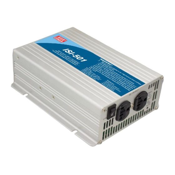
- Page 1 040-06-409-042-EH-0614.pdf ISI-501 Series Off-Grid Solar Inverter User Manual...
-
Page 2: Table Of Contents
040-06-409-042-EH-0614.pdf Off-Grid Solar Inverter User Manual Table of Contents 1.Safety Guidelines ................... 2.Introduction .................... 2.1 Features ................... 2.2 Main Specification ................3.User Interface Panel ................3.1 Front Panel ..................3.2 LED indicator on Front Panel ............3.3 Rear Panel ..................4.Output Voltage and Frequency Settings .......... -
Page 3: Safety Guidelines
040-06-409-042-EH-0614.pdf 1.Safety Guidelines (Please read through this manual before assembling the Inverter) ‧Risk of elect rical sho ck and e nerg y hazard. All failures sho uld be examined by a qualified tec hnician. Ple ase do n ot remove the case of the inv erte r by you rself! ‧Plea se d o no t install the inverter in places with hig h moisture o r nea r wa ter. -
Page 4: Main Specification
040-06-409-042-EH-0614.pdf ‧AC o utput voltage regulation : 3% ± ‧H igh effic iency up to 88% ‧Built in M PPT solar ch arger, M PPT efficiency: 98% (Typ.) ‧Adjustable ou tput voltage and freq uency ‧LED indication fo r ope ration and battery capacity ‧Battery low a larm (with ele ctrically iso lated dry contact) ‧R em ote O N/O FF function ‧C om pliance to FCC / CE regulations... -
Page 5: Led Indicator On Front Panel
040-06-409-042-EH-0614.pdf LED Indicator (Status): Displays the operation status of the ISI-501. LED Indicator (Battery): Displays remaining capacity of battery. Function Setting: Output voltage and frequency can be set through this button. P ow er O N/O FF S witch : Th e inve rt er will tu rn OFF if the s witc h is in the OFF position. -
Page 6: Output Voltage And Frequency Settings
040-06-409-042-EH-0614.pdf Battery Low Alarm: This is an electrically isolated dry contact which can provide the user with an external control signal. Users will be alarmed of a low battery when the two pins are open and the ISI-501 makes a "beep" sound. Battery Status C onnector Sta tus Alarm... - Page 7 040-06-409-042-EH-0614.pdf AC OUTPUT Status Ba tter y Use an i nsu la ted pl ast ic Se tting st ick to press on t he "Set ti ng" bu tton Figure 4.1 Adjustin g output voltage and frequen cy Table 4-1 Voltage & Frequency Chart O/P Voltage 100 Vac 110Vac...
-
Page 8: Operating
040-06-409-042-EH-0614.pdf 5.Operation System On Battery Low Shutdown Auto Recovery (SW-ON) Protection AC Output 14.4/28.8/57.6V Battery Voltage 13/26/52V 10.5/21/42V Charger Status Figure 5 .1 O peration Sequence t1 : Wh en us er turns on the I SI-501 , ba ttery vo ltag e wi ll be sens ed. If battery voltage is greater than 13/26/52V, it means the battery is adequately charged and the charger circuit will remain de-activated to prevent overcharging. -
Page 9: Protection
040-06-409-042-EH-0614.pdf 6.Protection 6.1 Input Protection (A)PV Module Reverse Polarity Protection: In the case where the user accidently reverses the polarity of th e PV mo dule, the ISI-501 interna l fus e will blow to protect o ther circuitr y. Please contact your neare st distribute r or send the inverter back to Mean Well for repair. - Page 10 040-06-409-042-EH-0614.pdf o ve r he a ted a nd c au s e d an g er. P le a s e r e fe r to ta bl e 7. 1 or c on s u lt w ith o ur distributors or us if you have any questions.
- Page 11 040-06-409-042-EH-0614.pdf (D)Suggested Mounting The four holes on the sides of the case allow the users to mount and fix the ISI-501 on a flat surface. (It is highly recommended the ISI-501 is placed horizontally. Also, please pay attention to the ventilation .) (E)Example of System Setup Leads should be as short as possible Greater...
-
Page 12: Troubleshooting
040-06-409-042-EH-0614.pdf Notes on O utput Loads: ISI-501 Series can power most equipments requiring an AC source of 500W continuously for a long time, but for certain type of load, this inverter may not work properly. (1 )Si n ce indu ctiv e loa d s o r mo tor b as ed e qui p me nts n eed a l a rge sta rt up current (6~10 times of its rated current), please make sure this startup current is less than the maximum current capability o f the ISI-501 . - Page 13 040-06-409-042-EH-0614.pdf...
- Page 14 + 49 89 43 10 91 91 dieter.hirthe@pewatron.com kurt.stritzelberger@pewatron.com kurt.stritzelberger@pewatron.com Sales Other Countries / Product Management Sensors Power Supplies E-Components PEWATRON AG Thurgauerstrasse 66 CH-8052 Zurich Physical Sensors DC-DC Converters Current Sensors Data Acquisition Switching Power Supplies Man Machine Interface...
Need help?
Do you have a question about the MEAN WELL ISI-501 Series and is the answer not in the manual?
Questions and answers