Table of Contents
Advertisement
Quick Links
Short Manual (Modbus-RTU)
Revisions ........................................................................................................................................... 2
1 Specifications ................................................................................................................................. 3
1.1 Performance Parameter ....................................................................................................... 4
1.2 Indicator .............................................................................................................................. 5
1.3 Dimensions.......................................................................................................................... 5
1.4 Standard flange ................................................................................................................... 6
1.5 Pinout Description ............................................................................................................... 6
2 Modbus-RTU Control .................................................................................................................... 7
2.1 Wiring ................................................................................................................................. 7
2.2 Debugging software description ......................................................................................... 8
2.1.1 Installation and wiring of debugging software ......................................................... 8
2.1.2 Debugging software instructions .............................................................................. 9
2.3 Modbus-RTU Description ................................................................................................. 12
2.3.1 Default Communication Parameters ...................................................................... 12
2.3.2 RTU Framing ......................................................................................................... 13
2.3.3 Register Mapping ................................................................................................... 13
2.3.4 Register Description ............................................................................................... 15
2.3.4.1 Initialization ................................................................................................ 15
2.3.4.2 Force ............................................................................................................ 15
2.3.4.3 Position ........................................................................................................ 16
2.3.4.4 Initialization State ....................................................................................... 16
2.3.4.5 Gripper State ............................................................................................... 17
2.3.4.6 Current Position .......................................................................................... 17
2.3.4.7 Save Parameter ............................................................................................ 18
2.3.4.8 Initialization Direction ................................................................................ 18
2.3.4.9 Slave Address .............................................................................................. 19
2.3.4.10 Baud Rate .................................................................................................. 19
2.3.4.11 Stop Bits .................................................................................................... 19
2.3.4.12 Parity ......................................................................................................... 20
2.3.4.13 Test I/O Parameters ................................................................................... 20
2.3.4.14 I/O Mode Switch ....................................................................................... 21
2.3.4.15 I/O Parameter Configuration ..................................................................... 21
3 I/O Control ................................................................................................................................... 23
All manuals and user guides at all-guides.com
Tel/Fax: 0755-82734836
AG-95 Gripper
Content
1
www.dh-robotics.com
Advertisement
Table of Contents

Related Manuals for DH Robotics Technology AG-95


Summary of Contents for DH Robotics Technology AG-95
-
Page 1: Table Of Contents
All manuals and user guides at all-guides.com Tel/Fax: 0755-82734836 www.dh-robotics.com AG-95 Gripper Short Manual (Modbus-RTU) Content Revisions ............................2 1 Specifications ..........................3 1.1 Performance Parameter ....................... 4 1.2 Indicator ..........................5 1.3 Dimensions.......................... 5 1.4 Standard flange ........................6 1.5 Pinout Description ....................... -
Page 2: Revisions
All manuals and user guides at all-guides.com Tel/Fax: 0755-82734836 www.dh-robotics.com Revisions Date Version Revised content First edition, write wiring instructions and 20200426 V1.0 command instructions Change some instructions , Update the description 20200904 V2.0 of IO mode Normal update, Add debugging software 20210401 V2.1 description... -
Page 3: Specifications
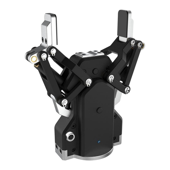
All manuals and user guides at all-guides.com Tel/Fax: 0755-82734836 www.dh-robotics.com 1 Specifications AG series are adaptive electric gripper, The number(AG-number) represents the maximum gripping stroke of the gripper. The gripper is equipped with a pair of parallel fingertips, which runs symmetrically during the movement. -
Page 4: Performance Parameter
Fz, the x-axis direction torque is Mx, the y-axis direction torque is My, and the z-axis direction torque is Mz. The AG-95 finger load table is shown in Table 1.2: Figure 1.2 Finger load diagram Table 1.2 AG-95 Finger load. -
Page 5: Indicator
·Object dropped state: green light blinking. 1.3 Dimensions The gripper hardware parameters contain the specific size of the gripper, the mounting hole, as shown in Figure 1.3(a), Figure 1.3(b). Figure 1.3 (a) Dimension drawing of AG-95 Figure 1.3 (b) Finger-tip installation dimension drawing... -
Page 6: Standard Flange
1.4 Standard flange The flange is used for the connection between AG-95 electric gripper and robot. The company provides standard flange, as shown in Figure 1.4. The gripper also supports custom flanges. Figure 1.4 Standard flange according to ISO 9409-1-50-4-M6 1.5 Pinout Description... -
Page 7: Modbus-Rtu Control
All manuals and user guides at all-guides.com Tel/Fax: 0755-82734836 www.dh-robotics.com 2 Modbus-RTU Control 2.1 Wiring Use the provided RS-485 to USB converter (see the schematic in Figure 1.1 below) to plug into a PC or other Controllers. Figure 2.1 RS485 Connection The outgoing line of clamping claw body can be changed according to the needs of customers. -
Page 8: Debugging Software Description
All manuals and user guides at all-guides.com Tel/Fax: 0755-82734836 www.dh-robotics.com 2.2 Debugging software description The debugging software is specially used to control the gripper and set debugging parameters on the computer. Because there is no RS485 interface in the computer, the USB to 485 module is needed to convert the interface to USB interface, which is convenient for the debugging and control of the gripper in the computer. -
Page 9: Debugging Software Instructions
All manuals and user guides at all-guides.com Tel/Fax: 0755-82734836 www.dh-robotics.com Figure 2.4 (a) installation interface 1 Figure 2.4 (b) driver installation interface 2.1.2 Debugging software instructions ‘ Before use, it is necessary to connect the corresponding wiring according to the instructions (see 2.1.1 Installation and wiring of debugging software). - Page 10 All manuals and user guides at all-guides.com Tel/Fax: 0755-82734836 www.dh-robotics.com Figure 2.5 main control interface The specific interface description is as follows: Interface description ·① Initialization and demonstration mode: the gripper needs to be initialized before operation to calibrate the zero point. The demonstration mode is a cyclic program. ·②...
- Page 11 All manuals and user guides at all-guides.com Tel/Fax: 0755-82734836 www.dh-robotics.com Figure 2.6 View If there are multiple 485 devices, sometimes the baud rate and ID number of the gripper need to be modified, the parameters can be modified in Modbus RTU parameters Figure 2.7 Modbus RTU parameters You can set and configure the gripper I / O parameters in [I / O parameters].
-
Page 12: Modbus-Rtu Description
All manuals and user guides at all-guides.com Tel/Fax: 0755-82734836 www.dh-robotics.com Figure 2.8 Modbus RTU parameters The steps of switching IO are as follows: Steps to switch IO mode ·① Open IO mode: open IO mode first. ·② Configure four groups of IO parameters: set the four groups of parameters of gripper, including position, force and speed. -
Page 13: Rtu Framing
All manuals and user guides at all-guides.com Tel/Fax: 0755-82734836 www.dh-robotics.com 2.3.2 RTU Framing This gripper uses the standard Modbus-RTU protocol. In RTU mode, the first field is the device address. The allowable characters transmitted for all fields are hexadecimal 0 ... 9, A ... F. Networked devices monitor the network bus continuously, including during the silent intervals. - Page 14 All manuals and user guides at all-guides.com Tel/Fax: 0755-82734836 www.dh-robotics.com Table 2.2 Basic Control register map High Function Description Write Read bytes bytes 0x01:initialization; Initialize the Initialization 0x00 0xA5: Fully Current setting gripper initialization Gripper’s Closing-force force 0x01 0x01 20-100 (%) force currently set reserve...
-
Page 15: Register Description
All manuals and user guides at all-guides.com Tel/Fax: 0755-82734836 www.dh-robotics.com 2.3.4 Register Description 2.3.4.1 Initialization This register is used to initialize the gripper. Write: If write 1 (0x01 hex) to this register, the gripper will be initialized (fingers move to the minimal or maximum position. -
Page 16: Position
All manuals and user guides at all-guides.com Tel/Fax: 0755-82734836 www.dh-robotics.com Read the closing force currently set (read): Send: 01 03 01 01 00 01 D4 36 Return: 01 03 02 xx xx crc1 crc2 2.3.4.3 Position This register is used to set the reference position of gripper's fingers, then the fingers will move to the position immediately. -
Page 17: Gripper State
All manuals and user guides at all-guides.com Tel/Fax: 0755-82734836 www.dh-robotics.com 2.3.4.5 Gripper State This register is used to store the Gripper state, you can get the state of gripper by reading this register. And the address is 0x0201. The description of this register is shown in Table 2.8. Table 2.8 Gripper State Function Address... -
Page 18: Save Parameter
All manuals and user guides at all-guides.com Tel/Fax: 0755-82734836 www.dh-robotics.com 2.3.4.7 Save Parameter This register is used to Save Parameter. Write 1 to this register to save all parameter, If you modified the I/O or communication parameters. The address is 0x0300. The description of this register is shown in Table 2.10. Table 2.10 Save Parameter Function Address... -
Page 19: Slave Address
All manuals and user guides at all-guides.com Tel/Fax: 0755-82734836 www.dh-robotics.com Return: 01 06 03 01 00 00 D8 4E 2.3.4.9 Slave Address This register is used to set Slave Address of gripper. The address is 0x0302. The description of this register is shown in Table 2.12. Table 2.12 Slave Address Function Address... -
Page 20: Parity
All manuals and user guides at all-guides.com Tel/Fax: 0755-82734836 www.dh-robotics.com The address is 0x0302. The description of this register is shown in Table 2.14. Table 2.14 Stop bits settings Function Address Description Write Read 0:1 stop bit Configure gripper 1:2 stop bits Stop Bits 0x0304 Current setting... -
Page 21: I/O Mode Switch
All manuals and user guides at all-guides.com Tel/Fax: 0755-82734836 www.dh-robotics.com Example: Control gripper by using first group of I/O parameter (write): Send: 01 06 04 00 00 01 49 3A Return: 01 06 04 00 00 01 49 3A 2.3.4.14 I/O Mode Switch This register is used to turn I/O Control Mode ON or OFF. - Page 22 All manuals and user guides at all-guides.com Tel/Fax: 0755-82734836 www.dh-robotics.com High- Function Description Write Read byte bytes 0x05 position 1 0-1000‰ I/O Group 1 0x06 force 1 20-100 % 0x08 position 2 0-1000‰ I/O Group 2 0x09 force 2 20-100 % 0x04 Current setting 0x0B...
-
Page 23: O Control
All manuals and user guides at all-guides.com Tel/Fax: 0755-82734836 www.dh-robotics.com 3 I/O Control The I/O mode is a common control method in industry. The grippers will monitor the pin states of Input 1 and Input 2 (0V and high resistance states). For these two pins, there will be four logic states:00,01,10,11. - Page 24 All manuals and user guides at all-guides.com Tel/Fax: 0755-82734836 www.dh-robotics.com Table 3.1 Input State INPUT 1 INPUT 2 Pin state Perform action I/O state Target position 1,target No wiring No wiring Group 1 force 1,target speed 1 Target position 2,Target No wiring Group 2 Force 2,Target Speed 2...
Need help?
Do you have a question about the AG-95 and is the answer not in the manual?
Questions and answers