Table of Contents
Advertisement
Advertisement
Table of Contents

Subscribe to Our Youtube Channel
Related Manuals for DH Robotics Technology AG-95


Summary of Contents for DH Robotics Technology AG-95
- Page 1 Product Manual (AG-95) Shenzhen DH Robotics Technology Co., Ltd.
-
Page 2: Table Of Contents
DH Robotics Technology Co., Ltd. www.dh-robotics.com Content 1 Specifications ..........................1 2 Connection methods ........................3 3 Connect and control ........................5 3.1 Introduction ......................... 5 3.2 Communication logic ......................5 3.3 Protocol format ........................6 3.4 Command Overview ......................7 3.5 Detailed command ...................... - Page 3 DH Robotics Technology Co., Ltd. www.dh-robotics.com 4.4.7.3 Setting of Gripper CAN Baud Rate ............. 32 4.4.7.4 Setting of Relevant Parameters of I/O Mode ..........32 4.4.8 Parameter Setting of Protocol Converter ............... 33 5. Robot Plugin ..........................35 5.1 UR Robot Plugin ....................... 35 5.1.1 Installation (UR + CB Series) ................
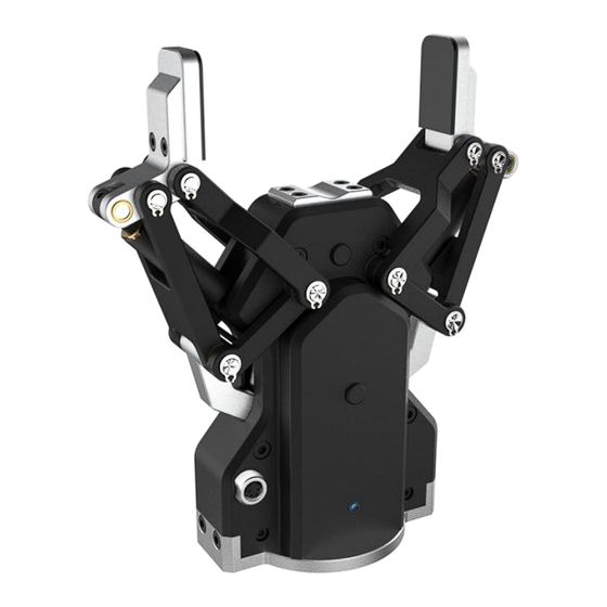
- Page 4 1 Product overview The electric gripper of AG-95 has two joints, which are respectively composed of multiple link mechanisms and one spring, as shown in Figure 1.1. The gripper can engage up to 5 contact points of contact with an object (two on each of the phalanges plus the palm). The fingers are under- actuated, indicating they have fewer motors than the total number of joints.
-
Page 5: Specifications
DH Robotics Technology Co., Ltd. www.dh-robotics.com 1.1 Specifications The specific parameters of AG-95 electric gripper are listed in Table 1.1. Specifications Maximum recommended load 3*kg Finger opening stroke 0-95mm Gripper force 45-160N Maximum finger opening and 136mm/s closing speed Supply voltage 24V DC±10%... -
Page 6: Connection Methods
2 Connection methods The electric gripper of AG-95 use CAN for communication, which supports CAN2.0A version. In order to communicate with other protocols, we develop protocol converter to support other communication protocol, such as TCP/IP , USB , RS485 IO .If the system itself supports CAN , you can also connect the gripper directly to the system without using a communication protocol converter. - Page 7 DH Robotics Technology Co., Ltd. www.dh-robotics.com Figure 2.2 Ethernet connection diagram...
-
Page 8: Connect And Control
3 Connect and control 3.1 Introduction The AG-95 adaptive Gripperuse aviation connector to connect the CAN network. It supports the CAN protocols version 2.0A. For environments without a CAN network, we have provided a protocol converter to transfer other interfaces (like USB, TCP/IP, RS485, I/O) to CAN2.0A. -
Page 9: Protocol Format
DH Robotics Technology Co., Ltd. www.dh-robotics.com 6. Command interval:It is recommended that the send interval between the command and the command is above 20 milliseconds. 7. Drop detection:The diameter of the object needs to be greater than 5mm. 3.3 Protocol format... -
Page 10: Command Overview
DH Robotics Technology Co., Ltd. www.dh-robotics.com Frame End:The command starts with 0xFB and the protocol converter will recognize this field to determine the end of the command. example:Initialization --- FF FE FD FC 01 08 02 01 00 00 00 00 00 FB 3.4 Command Overview... -
Page 11: Force
DH Robotics Technology Co., Ltd. www.dh-robotics.com When the Sub-Function register value is 0x02, the function of this command is to initialize gripper or read whether finish initialization. initialization : Send :FF FE FD FC 01 08 02 01 00 00 00 00 00 FB Receive :FF FE FD FC 01 08 02 01 00 00 00 00 00 FB... -
Page 12: Feedback
DH Robotics Technology Co., Ltd. www.dh-robotics.com Set 60% position: Send :FF FE FD FC 01 06 02 01 00 3C 00 00 00 FB Receive :FF FE FD FC 01 06 02 01 00 3C 00 00 00 FB Read current position:... - Page 13 DH Robotics Technology Co., Ltd. www.dh-robotics.com 0x08 0x01 Control Group 2 grip 0x09 0x00/0x01 Read/Write Enable I/O Mode 0x0A 0x00/0x01 Read/Write Group 1 Force 2 0x0B 0x00/0x01 Read/Write Group 2 Force 2 I/O mode is a simple communication mode. The status of the input pin is detected by the protocol converter with I/O interface, and the command is sent to the gripper according to the current pin status.
-
Page 14: Can Id
DH Robotics Technology Co., Ltd. www.dh-robotics.com Receive :FF FE FD FC 01 10 07 01 00 3C 00 00 00 FB Send :FF FE FD FC 01 10 0B 01 00 5A 00 00 00 FB (Set Group 2 Force 2 Receive :FF FE FD FC 01 10 0B 01 00 5A 00 00 00 FB... -
Page 15: Firmware Version
DH Robotics Technology Co., Ltd. www.dh-robotics.com Receive:FF FE FD FC 02 12 01 00 00 02 00 00 00 FB OR: (when you don’t know current ID) Send:FF FE FD FC 00 12 01 01 00 00 00 00 00 FB (use ID=0 to read ID)... -
Page 16: Object Droped
DH Robotics Technology Co., Ltd. www.dh-robotics.com 3.5.9 Object Droped Function Sub-Function Read/Write Reserve Data Function register register 0x15 0x01/02 0x00/0x01 0x00 Integer Object droped feedback Open object droped feedback function : FF FE FD FC 01 15 01 01 00 01 00 00 00 FB... -
Page 17: Protocol Converter
DH Robotics Technology Co., Ltd. www.dh-robotics.com 4 Protocol Converter The protocol converter (CTS-B1.0) is to convert communication protocols between the controller and the DH’s gripper, in order to make the gripper compatible with controllers as many as possible. In addition, the protocol converter (CTS-B1.0) has multiple working modes according to the communication protocols to be converted. -
Page 18: Parameter Configuration Mode
DH Robotics Technology Co., Ltd. www.dh-robotics.com the default parameters. 4.2 Parameter Configuration Mode Switch Status (Mode Number) Working Mode Parameter configuration mode 0 0 0 0 (0) In this mode, parameters of other modes of the protocol converter can be set by the software, such as modifying the IP address of the protocol converter used as a TCP server. -
Page 19: Tcp Client Mode
DH Robotics Technology Co., Ltd. www.dh-robotics.com 2. Make sure that the protocol converter is turned off and the USB cable is not connected. 3. Set the red DIP switches of the protocol converter to 1000 (with the DIP switch 1 in the upper position, and the DIP switches 2, 3 and 4 in the lower position). -
Page 20: Tcp Server Mode
DH Robotics Technology Co., Ltd. www.dh-robotics.com 4. Turn on the protocol converter. 5. If the setting is successful, the network port of the protocol converter will light up or flicker and the gripper indicator will flicker in red. 6. If the setting fails, check whether the operation is correct. -
Page 21: Rs485 Mode
DH Robotics Technology Co., Ltd. www.dh-robotics.com 24V power supply to the protocol converter through the DC power cable, and the control device through the network cable. 2. Make sure that the protocol converter is turned off and the USB cable is not connected. -
Page 22: I/O Mode
DH Robotics Technology Co., Ltd. www.dh-robotics.com converter with the controller through the 485 bus (485-A corresponding to 485-A, and 485-B corresponding to 485-B). 2. Make sure that the protocol converter is turned off and the USB cable is not connected to the controller at the moment. - Page 23 DH Robotics Technology Co., Ltd. www.dh-robotics.com 1: Output the low level 0V, and Output indicator is ON; 0: Output the high-impedance status , and the Output indicator is OFF; ② Status of the switch 1: OFF 1: Output the high level 24V, and the Output indicator is ON;...
-
Page 24: Can2.0A Mode
DH Robotics Technology Co., Ltd. www.dh-robotics.com IO Status (IN1 IN2) Command Content The gripper performs the first set of actions. The gripper performs the second set of actions. The gripper performs the third set of actions. The gripper performs the fourth set of actions. -
Page 25: Installation And Use Of Debugging Software
DH Robotics Technology Co., Ltd. www.dh-robotics.com CAN L). 3. Make sure that the protocol converter is turned off and the USB cable is not connected 4. Set the red DIP switches of the protocol converter to 1110 (with the DIP switches 1, 2 and 3 in the upper position, and the DIP switch 4 in the lower position). - Page 26 DH Robotics Technology Co., Ltd. www.dh-robotics.com (Name explanation: W7: Windows 7; W10: Windows 10; W8: Winows 8;64bits: 64-bit system; 32bits: 32-bit system) 1. Select the appropriate driver version according to the computer system version and bits, and click “Next”. 2. Fill in the registration information and click “Next”.
- Page 27 DH Robotics Technology Co., Ltd. www.dh-robotics.com 4. The driver installation wizard will pop up. Click “Next”. 5. After the successful installation, the following interface will appear. Click “Finish”. 6. Check whether the driver is normal. Set the protocol converter to USB mode, and connect the computer via the USB cable.
-
Page 28: User Interface
DH Robotics Technology Co., Ltd. www.dh-robotics.com protocol converter to USB mode). 4.4.3 User Interface The interface is mainly composed of three parts: gripper control zone on the left, communication control zone in the middle, and parameter setting zone on the right. -
Page 29: Connection Mode And Port Setting
DH Robotics Technology Co., Ltd. www.dh-robotics.com This figure shows the interface of the communication control zone, which consists of the following parts from top to bottom and from left to right: Connection mode selection, Port setting, and Status display, Connect button, Initialize button, and Disconnect button. -
Page 30: Communication Control And Status Display
DH Robotics Technology Co., Ltd. www.dh-robotics.com TCP Client: The computer worker as a TCP client in this mode. The protocol converter should be set to the TCP Server mode. According to the protocol converter IP and port number you set, modify the target IP and port. When the protocol converter is used as the TCP server, the default IP is 192.168.1.29, and the monitoring port is 8888. -
Page 31: Gripper Control
DH Robotics Technology Co., Ltd. www.dh-robotics.com The first status (left): default status (unconnected). Only the “Connect” can be clicked. You must perform connection, setting and connection in the previous section before clicking this button. The second status (middle): when the gripper is successfully connected, the “Initialize” button and “Disconnect”... -
Page 32: Parameter Setting Zone
DH Robotics Technology Co., Ltd. www.dh-robotics.com Position control zone: consisting of the Close button, Close control button, position display bar, Open control button, and Open button. Close Force control zone: consisting of the Min button, - button, force display bar, + button, and Max button. -
Page 33: Gripper Parameter Setting
DH Robotics Technology Co., Ltd. www.dh-robotics.com It is divided into the gripper parameter setting zone on the left and protocol converter parameter setting zone on the right. Gripper parameter setting zone: Display the gripper firmware version number, and set whether to initiate feedback after initialization;... -
Page 34: Gripper Setting Instructions
DH Robotics Technology Co., Ltd. www.dh-robotics.com Note: The firmware version of the gripper varies, so the settable functions may be different. 4.4.7 Gripper Setting Instructions 4.4.7.1 Setting of Activated Feedback of Initialization This option must be checked when UR and AUBO plug-ins are used. -
Page 35: Setting Of Gripper Can Baud Rate
Be sure that the returned command is received. Then restart the gripper to activate the setting. 4.4.7.4 Setting of Relevant Parameters of I/O Mode Relevant data of the I/O mode is stored in the gripper. The AG-95 gripper has two groups of parameters (two groups of opening and closing) in the I/O mode. The “... -
Page 36: Parameter Setting Of Protocol Converter
DH Robotics Technology Co., Ltd. www.dh-robotics.com Fill in the parameters, click “ ”and wait for the command sending/receiving zone to automatically send and receive four commands. Click “ ” to test the Open/Close position of the corresponding I/O group. 4.4.8 Parameter Setting of Protocol Converter... - Page 37 DH Robotics Technology Co., Ltd. www.dh-robotics.com IP Address: static IP address of the protocol converter, 192.168.1.29 in the above figure. It must within the same network segment as the connected router. Gateway: The gateway of the protocol converter is directly connected with the control device.
-
Page 38: Robot Plugin
5.1 UR Robot Plugin 5.1.1 Installation (UR + CB Series) For integration with Universal robots, AG-95 is compatible with UR3, UR5, and UR10. It contains the CB3.1 controller and above and control software with 3.34xx teach pendant and above. 1. Insert the DH’s USB flash disk with plug-in files into the USB port of the teach pendant. - Page 39 DH Robotics Technology Co., Ltd. www.dh-robotics.com 3. Enter the UR plug-in setting page and click “+” to add the plug-ins to be used in the robot gripper. 4. Select “URCap_AG_95_1.3.1_Client_T190301RE.urcap” in the USB flash disk. 5. Click “Open” at the bottom of the screen.
-
Page 40: Robot Setup (Ur+ Cb Series)
DH Robotics Technology Co., Ltd. www.dh-robotics.com 5.1.2 Robot Setup (UR+ CB series) • Connect the gripper and protocol converter via the aviation plug cable. • Connect the UR control cabinet and protocol converter via the network cable (do not connect the USB cable). - Page 41 DH Robotics Technology Co., Ltd. www.dh-robotics.com • If all settings are normal, the network port indicator of the protocol converter will light up or flicker. In this case, the protocol converter will work as the TCP server. 1. Enter the UR setting interface.
-
Page 42: Operating Instructions (Ur + Cb Series)
DH Robotics Technology Co., Ltd. www.dh-robotics.com 4. Click “Apply” (it is recommended to restart the UR robot after modifying the network settings). 5.1.3 Operating Instructions (UR + CB Series) 1. Click “Program Robot” in the main menu interface to enter the program interface. - Page 43 DH Robotics Technology Co., Ltd. www.dh-robotics.com 4. Enter the new program interface, click “Installation” in the toolbar, and connect the gripper. 5. Click “DH Robotics” under “Installation” to enter the gripper setting interface of DH Robotics.
- Page 44 DH Robotics Technology Co., Ltd. www.dh-robotics.com • In the IP Address and Port input boxes, enter the IP address and port number of the protocol converter. • Click “Connect” and wait for connection. When “Disconnect” changes into “Connect”, it means that connection succeeds.
- Page 45 DH Robotics Technology Co., Ltd. www.dh-robotics.com 8. Select “AG-95 Gripper” and add the plug-in control program. 9. Set the gripper.
-
Page 46: Installation (Ur+ E Series)
• Click “Save” to save this group of data into the program node. 5.1.4 Installation (UR+ e Series) For integration with universal robots, AG-95 is compatible with URe3, URe5, URe10 and URe16. It contains the e-Series controller and above and control software with 5.4.3 demonstrator and above. - Page 47 DH Robotics Technology Co., Ltd. www.dh-robotics.com 3. Click “Network” under “System”, set the “Static Address” to be consistent with the protocol converter setting, and click “Apply”. 4. Click “URCaps” in the system setting interface and then click “+” in the URCaps interface.
-
Page 48: Robot Setup (Ur+ E Series)
DH Robotics Technology Co., Ltd. www.dh-robotics.com 5. Select the file “URCap_AG_95-1.3.1_Client_T190301RE.urcap” in the USB flash disk, and click “Open”. 6. Click “Restart”. Thus, the installation is finished. 5.1.5 Robot Setup (UR+ e Series) • Connect the gripper and protocol converter via the aviation plug cable. -
Page 49: Operating Instructions (Ur+ E Series)
DH Robotics Technology Co., Ltd. www.dh-robotics.com • Change the red DIP switches of the protocol converter to 1100, and turn on the protocol converter. • If all settings are normal, the network port indicator of the protocol converter will light up or flicker. -
Page 50: Script Commands (Universal For Ur+ Cb Series And E Series)
DH Robotics Technology Co., Ltd. www.dh-robotics.com 3. Create a new robot program, find the AG-95 gripper node on the URCaps interface, and add this node into the robot program. 4. The gripper control function has been added into the URCaps node. This node can control the position and force of the gripper, such as gripper movement to a specific Open/Close position or gripping of an object with the preset force. -
Page 51: Hanwha Robot Plugin
DH Robotics Technology Co., Ltd. www.dh-robotics.com Function Script Interface Remarks Position setPos(0) Value: 0-100 Read position var = getPos() Read the position feedback by assigning a value (0-100). Close force setForce(90) Value: 0-100 Read Close force var = getForce() Read the Close force feedback by assigning a value (0-100). - Page 52 DH Robotics Technology Co., Ltd. www.dh-robotics.com 4. Select the plug-in file in the USB flash disk, i.e. “DH_AG95_Plugin.asar” under the directory shown in this figure. Click “OK”. 5. Click “Restart” in the lower right corner, and restart the system.
-
Page 53: Robot Setup
DH Robotics Technology Co., Ltd. www.dh-robotics.com 5.2.2 Robot Setup • Connect the gripper body and protocol converter via the aviation plug cable. • Connect the Hanwha control cabinet and protocol converter via the network cable (do not connect the USB cable). -
Page 54: Operating Instructions
DH Robotics Technology Co., Ltd. www.dh-robotics.com • If all settings are normal, the network port indicator of the protocol converter will light up or flicker. In this case, the protocol converter will work as the TCP server. 1. Install the plug-in, connect the hardware, and start the demonstrator software HCR Rodi. - Page 55 DH Robotics Technology Co., Ltd. www.dh-robotics.com • If all settings are normal, the gripper will be initialized, and the position and force setting interface will appear. • The input boxes and operation buttons in the two lines below are used to control the position and force of the gripper.
-
Page 56: Script Commands
DH Robotics Technology Co., Ltd. www.dh-robotics.com • “ ” means the corresponding option is selected, while “ ” means that the corresponding option is not selected. 5. Check “Skip” in the upper right corner to disable this step. “ ” means that the option is selected when this step is disabled, while “... -
Page 57: Aubo Robot Plugin
5.3 Aubo Robot Plugin 5.3.1Installation For integration with Aubo robots, AG-95 is compatible with Aubo i3, i5, i7 and i10. It contains the Aubo control system of 4.3.0 and above (it is recommended to upgrade the Aubo system to 4.5 and above). -
Page 58: Robot Setup
DH Robotics Technology Co., Ltd. www.dh-robotics.com 5.3.2 Robot Setup The Aubo robot plug-ins have multiple connection modes. Take the use of Aubo control cabinet as TCP client as an example. • Connect the gripper body and protocol converter via the aviation plug cable. -
Page 59: Operating Instructions
DH Robotics Technology Co., Ltd. www.dh-robotics.com • Click “Save” to save the settings, and restart the Aubo robot to enable the network settings. 5.3.3 Operating Instructions 1. Open the demonstrator, and click “Extension” in the toolbar to enter the “Dhrobotics2F”... - Page 60 DH Robotics Technology Co., Ltd. www.dh-robotics.com 5. Click “Online Programming” in the above figure to enter the programming interface. Select “Conditions” on the left. Three condition command options will appear. Select “Peripherals”. The option “2 Finger Gripper” will appear on the right.
-
Page 61: Script Commands
DH Robotics Technology Co., Ltd. www.dh-robotics.com • Click “Control Gripper” to enable the gripper to execute this action. • Click “OK” to save this group of data into the program node. • Click “Delete” to delete this node from the program. -
Page 62: Maintenance
DH Robotics Technology Co., Ltd. www.dh-robotics.com 6 Maintenance 6.1 Daily Cleaning Recommended Optimal Tools Required Parts Required Cleaning Interval Once a week (once a day in 1. Circlip pliers None dirty environments) 2. Dry towel or tissue Note: The gripper surface is not waterproof, so it must be cleaned with a dry towel or tissue. -
Page 63: Periodic Inspection And Maintenance
DH Robotics Technology Co., Ltd. www.dh-robotics.com Inspection Interval Tools Required Parts Required 1,000,000 gripping cycles or M3 Allen screwdriver One pair (2) of fingertips (with when damaged seriously silicone pads) of DH’s 2-finger adaptive robot Contact the technical support department of DH Robotics for fingertip replacement. -
Page 64: Part Numbers
Fingertip Directly grip an object at the end. AG95-FIN-001 Standard coupling Coupling connected to the end of robot AG95-CPL-001 USB flash disk Include all electronic data of AG-95 AG95-UFD-001 (data) Power cable For power supply to the gripper AG95-PWC-001 Aviation plug For communication between the gripper and AG95-CLB—05... -
Page 65: Common Faults And Troubleshooting
DH Robotics Technology Co., Ltd. www.dh-robotics.com 7 Common Faults and Troubleshooting 7.1 Meanings of Gripper Indicators The gripper has three indicators: red, green and blue. They have different meanings, depending on the gripper status. Not initialized: The red indicator flickers, while the other indicators remain OFF. - Page 66 DH Robotics Technology Co., Ltd. www.dh-robotics.com Switch Status (Mode Switch Status (Mode Working Mode Working Mode Number) Number) Parameter 0000(0) configuration 0010(4) RS485 mode mode 1000(1) USB mode 1010(5) RS485 Modbus mode 0100(2) TCP client mode 0110(6) IO mode 1100(3)
- Page 67 DH Robotics Technology Co., Ltd. www.dh-robotics.com connected with the control device. Q8: The gripper cannot be controlled after the normal connection. A8: There are several parts, so they must be checked one by one. When the connection is allowed, failure is usually caused by the aviation plug cable, protocol converter, and gripper body.
-
Page 68: Certificates
DH Robotics Technology Co., Ltd. www.dh-robotics.com 8 Certificates... - Page 69 DH Robotics Technology Co., Ltd. www.dh-robotics.com...
- Page 70 DH Robotics Technology Co., Ltd. www.dh-robotics.com...
-
Page 71: Warranty And Statement
9 Warranty and Statement The warranty period of the AG-95 electric gripper of DH Robotics is one year, calculated from the date of receiving the product. During the warranty period, DH Robotics will perform maintenance or replacement of defective products free of charge, including but not limited to: The electric gripper cannot be opened or closed. -
Page 72: Contact Us
DH Robotics Technology Co., Ltd. www.dh-robotics.com 10 Contact us Tel: +86 755 82734836 Email: info@dh-robotics.com Address: A401, Industrialization Building, Virtual University Park, Yuexing 3 Road, Nanshan, Shenzhen Postcode: 517057 Official website: www.dh-robotics.com...
Need help?
Do you have a question about the AG-95 and is the answer not in the manual?
Questions and answers