
Related Manuals for GEO Calibration 4000 EXP

Summary of Contents for GEO Calibration 4000 EXP
- Page 1 MODEL 4000 EXP User Manual English Deutsch GEO Calibration Inc. 2190 Smithtown Avenue Francais Ronkonkoma, NY 11779...
-
Page 2: Table Of Contents
UUTs (UNITS UNDER TEST) ..................... 23 REFERENCE STANDARD RECALIBRATION ... 24 CONTROL PROBE / REFERENCE SENSOR ................24 ENTERING MODEL 4000 EXP OFFSETS ....24 UNIT OFFSET CALIBRATION VIA PUTTY ................26 ACCESSING THE DEVICE MANAGER ..................26 READING THE COM PORT ....................... 27 INSTALLING PUTTY ........................ - Page 3 PROBE REMOVAL ........................37 PROBE REPLACEMENT ......................38...
-
Page 4: Introduction
INTRODUCTION MESSAGE FROM GEO CALIBRATION Thank you for purchasing the GEO Calibration Model 4000 EXP humidity and temperature generator/ calibrator. We look forward to providing you the highest quality technical support as you become familiar with your new humidity and temperature calibrator. -
Page 5: Product Warranty
LIMITED WARRANTY AND LIMITATION OF LIABILITY Each GEO Calibration product is warranted to be free from defects in material and workmanship under normal use and service. The warranty period is one year and begins on the date of shipment. Parts, product repairs, and services are warranted for 90 days. -
Page 6: Unpacking Instructions
UNPACKING INSTRUCTIONS Once you have removed the Model 4000 EXP from its external packaging, please visually inspect the unit for damage. If damage is found, please immediately contact your supplier. CALIBRATOR APPLICATIONS The GEO Model 4000 EXP Humidity Calibrator generates and maintains a controlled humidity and temperature environment for the purpose of testing or calibrating humidity and temperature sensors, also known as hygrometers. -
Page 7: Standard Packing Check List
STANDARD PACKING CHECK LIST Within the Shipped Case Part Number Description 01-450-00-0000 Model 4000 EXP Expansion Chamber 01-450-01-0034 Desiccant Tank 01-450-01-0041 01-450-01-0041 Model 4000 EXP Power Supply 01-450-07-0039 Model 4000 EXP Acrylic Base 01-200-36-0002 Control Probe 01-200-01-0035 Model 4000 EXP Accessories Kit... - Page 8 STANDARD PACKING CHECK LIST Within the Accessories Box Part Number Description 01-001-00-0017 6 Port Door Square with 6 Plugs 01-001-66-0001 GEO Knobs (1 pack) 01-200-01-0036 01-200-01-0036 GEO Bungs (7 pack) Calibration Documents Part Number Description Factory Calibration Report 01-999-99-0001 3rd Party Calibration Certification (IF ORDERED)
-
Page 9: Visual Item Check List
VISUAL ITEM CHECK LIST Listed below are standard contents included with the purchase of a new Model 4000 EXP. Humidity Generator Desiccant Tank Power Supply GEO Calibration Pre-Filled with molecular sieve Model 4000 EXP P/N: 01-450-01-0034 P/N: 01-450-01-0041 P/N:01-450-00-0000 Model 4000 EXP Acrylic... -
Page 10: Accessories Box Contents
VISUAL ITEM CHECK LIST CALIBRATION M4000 EXP Accessories Calibration Documents Contents: See Below P/N: 01-200-36-0013 ACCESSORIES BOX CONTENTS 7 Piece Bung Kit 6 Port Door Square with 4 Piece GEO Knob Kit 6 Plugs P/N: 01-200-01-0036 P/N: 01-001-66-0001 P/N: 01-001-00-0017... -
Page 11: Accessories Bag Contents
ACCESSORIES BAG CONTENTS USB Cable Mains Power Cord Fill Syringe (50 mL) (A to A) P/N: 01-200-46-0001 P/N: 01-200-69-0001 P/N: 01-450-36-0003 01-450-36-0003 P/N: 01-200-46-0002 4 AMP Fuse Set Ultrasonic Wick And Ultrasonic Extraction Ultrasonic Transducer Tool P/N: 01-450-75-0001 P/N: 01-450-36-0002 P/N: 01-200-85-0001 01-450-01-0019... -
Page 12: Available Accessories
AVAILABLE ACCESSORIES Replacement Replacement Replacement Control Probe Fill Tube Desiccant HC2-S HygroClip control probe P/N: 01-450-36-0004 P/N: 01-200-36-0002 P/N: 01-450-36-0003 ISO 17025 System Chilled Mirror 971 Door Recalibration Door P/N: P/N: 01-001-00-0029 P/N: 01-001-00-0010 01-999-99-0004 Drawer Door Silicone Adapter Variations (Regular and Slimline) 01-001-00-0026 P/N:... - Page 13 AVAILABLE ACCESSORIES Grommets / Bungs M36 are for Standard Hygrometers PG36 are for Chilled Mirror Adapters Bung Size Port Size Part Number Type 01-004-09-0001 0.000 0.000” 3.175 01-004-09-0002 0.125” 01-004-09-0003 6.350 0.250” 0.375” 01-004-09-0004 9.525 31.00 Regular 1.22” 01-004-09-0005 12.700 0.500”...
-
Page 14: Unit Diagram And Parts Listing
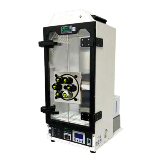
UNIT DIAGRAM AND PARTS LISTING Below you will find a diagram of the Model 4000 EXP’s various operational parts. FRONT DESCRIPTIONS Transparent Door Fill Port Drain Port Fill Level Indicator Ultrasonic Test Control Panel Power Switch Control / Reference Probe... -
Page 15: Quick Start Guide
QUICK START GUIDE Read Before Turning On The Unit After receiving the unit, open the door to let the chamber dry for 10 minutes. Use soft paper tower to wipe the water in the chamber if needed. Turn on the unit and set the temperature to 30 °C and humidity to 30 % to let the unit settle, approximately for 20 minutes (first time only). -
Page 16: Replacing The Desiccant
REPLACING THE DESICCANT Supplies Needed External Desiccant Desiccant Tank Desiccant Canister Remove the Desiccant Canister Remove the tubes from both unit and desiccant canister. To remove the tubes from desiccant, press the fitting first and pull to remove. Locate the Desiccant Seal Remove the seal screws by turning clockwise and pull to remove. - Page 17 Fill with Desiccant The desiccant canister takes approximately 12.5 lbs of desiccant material. Reseal the Desiccant Canister Put the cover back and reseal the screws.
-
Page 18: Filling The Reservoir
FILLING THE RESERVOIR Supplies Needed Distilled Water Fill Syringe Only Locate the Fill Port The port is labeled and located on the middle lower portion of the front panel. Remove the Fill Cap Rotate Counter-Clockwise to remove. Fill Syringe with Distilled Water Attach Fill Syringe to Fill Port Press the fill syringe tip into the fill port, then rotate the cap clockwise to secure. - Page 19 FILLING THE RESERVOIR Elevate and Fill Syringe - Pour distilled water into the elevated tube body. - Take care not to insert any air into the reservoir. - Monitor the water level indicator while filling. Loosen and Remove Syringe Turn the fill syringe tip counter-clockwise to loosen. Re-Install the Fill Cap Turn the cap clockwise to tighten the cap and seal the fill port.
-
Page 20: Unit Operation (Pid Controller)
UNIT OPERATION (PID CONTROLLER) Observe the Display Current Temperature Top Right Current Relative Humidity Bottom Right Programmed Temperature Middle Left Programmed Relative Humidity Bottom Left Changing Humidity & Temperature Pressing the “Next” button activates the set-point toggle. The selected field will repeatedly flash its current programmed value. -
Page 21: General Specifications
GENERAL SPECIFICATIONS TRANSFER STANDARD No Charge CALIBRATION TO (17025 TRACEABLE TO NIST) 17025 Validation (Additional Fees Apply) CERTIFICATE TEMPERATURE Ambient +/-5 °C HUMIDITY@18 °C 10 % to 70 % RH CONTROLLED RANGE HUMIDITY@23 °C 10 % to 90 % RH HUMIDITY@28 °C 10 % to 70 % RH TEMPERATURE... -
Page 22: Consumables
CONSUMABLES RESERVOIR 600 ml SPILL RESISTANT WATER REQUIRED FLUID Distilled Water Only EST. REFILL PERIOD 1 Week (Typical) *Depends on Usage FILL INDICATOR Floating Ball TYPE Molecular Sieve REPLACEMENT When Indicating Desiccant is 3/4 Used DESICCANT REPLACEMENT FREQUENCY Depends Entirely on User Workload LOCATION External FASTENER... -
Page 23: Calibration
Measure the diameter of the UUT to ensure it will fit inside the chamber. Ensure the door is securely fastened to the chamber. Insert UUT Insert your UUT at least 3 inches into the Model 4000 EXP chamber. Program Unit Set-points Allow the unit to reach the programmed set-points and settle. -
Page 24: Reference Standard Recalibration
Control Probe / Reference Sensor Overview The Model 4000 EXP functions through the use of a dual PID controller. This controller takes the hu- midity and temperature values from an internal capacitance probe and further performs calculations that are then used to generate the user entered humidity and temperature set points. This sensor is factory calibrated, and upon request, additionally calibrated by an ISO 17025 accredited laboratory using either a chilled mirror or two-pressure primary reference standard. - Page 25 REFERENCE STANDARD RECALIBRATION Self Recalibration Procedure To read the recalibration procedure of the control / reference probe, please refer to the unit’s user manual, and the HW4 software manual found at the following URLs as of publication of this manual: https://s.campbellsci.com/documents/ca/manuals/hc2-s3-l_man.pdf https://goo.gl/n7qE1G https://www.instrumart.com/assets/rotronic-hygroclip2-probes-manual.pdf...
-
Page 26: Unit Offset Calibration Via Putty
USB Port Unit Offset Calibration via PuTTY The Model 4000 EXP also allows users to make two, single point adjustments for both temperature and humidity. It is recommended that users recalibrate their unit as needed to fit their overall uncer- tainty requirements. -
Page 27: Reading The Com Port
ENTERING MODEL 4000 EXP OFFSETS Reading the COM Port At this time, plug the unit’s power supply into an approved power source. Plug the USB mouse and keyboard into the Unit. Toggle both the power switches to the “ON” position. -
Page 28: Connecting Through Putty
ENTERING MODEL 4000 EXP OFFSETS Connecting Through PuTTY In PuTTY, select Session menu under Category on the left Input your COM Port (reference Reading the Serial Port instruction from above) into the Serial line field Under Connection type, select Serial... -
Page 29: Changing Humidity And Temperature Offsets
ENTERING MODEL 4000 EXP OFFSETS Changing Humidity and Temperature Offsets PLEASE NOTE: #.# is a placeholder In the following instructions, replace # with your desired integers. (For example, #.# would become 1.2 or -0.2) Temperature: type TOFFSET #.# and press the Enter key. The unit will query and display the tem- perature offset. -
Page 30: Safety Warning
Make sure the ground conductor in the power cord is connected to a functioning ground. Disruption of the ground could put voltage on the chassis that could cause death. ● Use the Model 4000 EXP only as specified, or the protection supplied by the Product can be compromised. ●... -
Page 31: Disposal Safety Information
TECHNICAL SUPPORT Locations GEO Calibration Inc 2190 Smithtown Avenue, Ronkonkoma, NY 11779, USA Tel.: +001 (631) 471 - 6157 ● Fax: +001 (631) 471 - 6158 support@geocalibration.com ● www.geocalibration.com © GEO Calibration Inc. 2019... -
Page 32: Repairs
Estimated Return Ship-Date is 15 business days from the date both the unit and a valid method of payment is received ● On the Purchase Order, please ensure the “Vendor Name” is GEO Calibration Inc., and the address is 2190 Smithtown Avenue, Ronkonkoma NY 11779 ●... -
Page 33: Service Schedule
MAINTENANCE SERVICE SCHEDULE ● Maintenance Recommendations: GEO Calibration recommends that the unit be annually shipped back to our facility for general maintenance. Daily Semi-Annual As Needed General Cleaning Refill Reservoir with Distilled (Use Proper Cleaning Control Probe Calibration Water Materials) -
Page 34: Indication Icons
COMM the GEO Software Required Application The BIT (Built in Test) has detected a FAULT condition which will not allow control of the chamber. For questions, please contact GEO Calibration.You may also visit our website at www.geocalibration.com for more assistance. -
Page 35: Draining The Unit
DRAINING THE UNIT Locate the Main Drain Port Turn the cap counter-clockwise to remove. Move the Unit to Table Edge Position a bowl shaped object underneath the unit to catch the drained water. Remove the Drain Cap Tilt the unit to ensure maximum water removal. Replace &... -
Page 36: Shelf Adjustment
SHELF ADJUSTMENT Adjusting Shelf Height The Model 4000 EXP features a removable shelf system. The instructions below detail how to change or remove the shelves to accommodate the different kinds of hygrometers you may en- counter as a calibration technitian. - Page 37 PROBE REMOVAL Locate Probe Position Free Probe from Brackets Loosen Metal Connector Twist towards the chamber opening to loosen. Remove Probe Head...
- Page 38 PROBE REPLACEMENT Locate Probe Connector Press Probe into Connector Slowly rotate the probe head as you press into the cabling body. You will feel the probe “seat” itself once the male - female parts align. Secure Metal Connector Twist the metal connector away from the chamber entrance to secure the probe head to the probe cabling body.
- Page 39 INDUSTRIES PHARMACEUTICAL MANUFACTURING CALIBRATION LABS BIOMEDICAL R&D FACILITIES FOOD PRODUCTION AUTOMOTIVE MANUFACTURING AEROSPACE HOSPITAL / MEDICAL CLEAN ROOMS For a complete product and accessory review, please visit our website: www.geocalibration.com CONTACT US: Email: Sales@GeoCalibration.com Sales@GeoCalibration. Website: www.GeoCalibration.com www.GeoCalibration. (631) 471 - 6157...
- Page 40 Proudly Made in the USA Email: Sales@GeoCalibration.com Website: www.GeoCalibration.com © 2019 GEO Calibration Inc. All rights reserved. Rev A...
Need help?
Do you have a question about the 4000 EXP and is the answer not in the manual?
Questions and answers