
Related Manuals for GEO Calibration 1000 SP

Summary of Contents for GEO Calibration 1000 SP
- Page 1 GEO CALIBRATION Model 1000 SP User operational guide 10/15/2015 Copyright @2015 All Rights Reserved GEO Calibration http://www.geocalibration.com/ 2190 Smithtown Ave 1(631)471-6157 Ronkonkoma NY 11779...
-
Page 2: Table Of Contents
Built in Test Heat Exchanger configuration ..................... 12 Built in Test Humidity Generator configuration ..................13 Error List ..............................13 GEO 1000 SP Windows application ......................14 Software capabilities ..........................14 Windows Application Installation Guide ....................15 Package Contents ..........................15 GEO 1000 SP USB installation ...................... - Page 3 GEO Windows Application | Usage ......................16 Main Screen ............................17 Experiments ............................17 Phase ............................... 18 Modbus Initial setup ..........................19 Panel Mode ............................. 20 Plot control.............................. 21 Reports ..............................21 Record Mode ............................21 Error codes ..............................22 Contact Information ............................
-
Page 4: Quick Start Guide
Quick Start Guide Filling the Water Reservoir Locate the Fill Port Locate the Fill Tube Remove Cover from Fill Port A fill tube is shipping standard with every purchase of a GEO Calibration calibrator. - Page 5 Gently Connect Tube to Fill Port Tilt the Unit Forwards Tilt forwards at a 10 degree angle while filling, to observe fill level. Fill the Syringe Reservoir Only use standard distilled water. Fill one 10 mL syringe at a time while watching the fill level. The water will naturally flow into the internal chamber reservoir.
-
Page 6: Draining Water For Transportation
Draining Water for Transportation Place Unit on Edge of Table Make sure the rear of the unit is over the edge of the table, with a bucket beneath. Tilt the Unit Towards Edge A book or other solid object may be placed under the front of the unit for stability. -
Page 7: Cleaning Instructions
Cleaning Instructions Open the Chamber Door Unscrew any visible fasteners and pull the door from the chamber with moderate force. Clean With Paper Towel Disinfect with Alcohol Wipes... -
Page 8: Desiccant Installation
Desiccant Installation Locate Desiccant Canister If indicating desiccant was included in your order, you should check to ensure the desiccant has blue color throughout, with no pink granules present. Locate the Two Bungs on Rear Make sure there are O-Rings inside of each bung. Push Desiccant into Bungs Make sure blue desiccant is on the left hand side. -
Page 9: Desiccant Removal
Desiccant Removal Unjoin Velcro Straps Loosen Velcro Straps Gently Pull Desiccant Pull with two hands using even force on both sides of the desiccant canister. Use thumbs to push out from the chamber body, as shown in image provided. -
Page 10: Refilling The Desiccant
Refilling the Desiccant Open Top Cover of Desiccant Save the spring, the sieve and the three white felt filters. Discard previous desiccant. Wipe the inside of the desiccant canister with a clean cloth. Beat filters clean of debris. Clean the sieve and the spring. Fill Canister with Desiccant (Assuming use of approved refill kit) Insert and push a white filter to the bottom. -
Page 11: Introduction
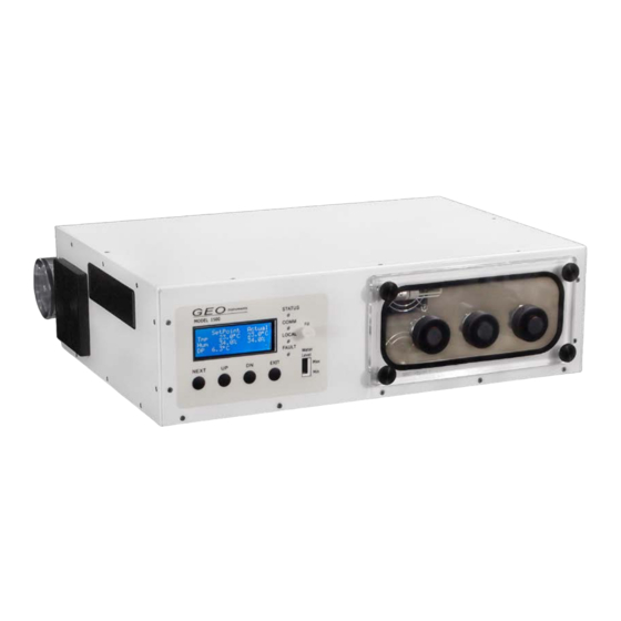
Operational Features Temperature and Humidity Control The GEO Calibration 1000 SP allows the user to generate a stable environment within its chamber. The unit can control and maintain the relative humidity and temperature in the chamber to within a resolution of 0.1% RH and 0.1°C respectively. The system accuracy is controlled via a NIST traceable internal probe. -
Page 12: Front Panel Operation
Front Panel Operation Main screen During normal operation the unit’s LCD screen shows the main menu which looks as below: Figure 1 Main menu This screen indicates the current set point temperature and humidity and the current actual temperature and humidity inside the chamber. From this screen the user can change the set point. The screen is organized as a grid. -
Page 13: Button Operation
Exit warming mode The ‘EXIT’ button has one additional use when the GEO Calibration 1000 SP is first started it may not have sufficient water vapor to allow the setting of higher relative humidity values. In this case the front panel will flash the word ‘WARMING’. -
Page 14: Status Lights
The ‘COMM’ light indicates the unit is receiving commands from the GEO 1000 SP Windows application. The ‘LOCAL’ light indicates that the unit’s environmental condition is being modified locally from the front panel. That is the current chamber environment has overridden the setting made by the GEO-DFB application. -
Page 15: Internal Probe Calibration Configuration
Internal Probe Calibration Configuration The probe calibration screen allows the user to introduce a calibration offset to the internal probe used to control the GEO Calibration 1000 SP chamber. This allows the user to calibrate the internal probe to an external reference. -
Page 16: Built In Test Humidity Generator Configuration
Built in Test Humidity Generator configuration The GEO Calibration 1000 SP has an internal humidity generator. This humidity generator is used as the source to the humidity within the chamber. To ensure that there is sufficient humidity generation capacity the unit humidity generator is kept in a warm standby state. To prevent damage from such conditions as insufficient water the generator temperature is not allowed to exceed a certain maximum threshold. -
Page 17: Geo 1000 Sp Windows Application
GEO 1000 SP Windows application Software capabilities The GEO-DFB Desktop Software controls the GEO 1000 SP unit. It has the following features: • Manually control current temperature and humidity of the GEO Calibration 1000 SP generator. • Monitor the temperature and humidity values of the internal control probe channel. -
Page 18: Windows Application Installation Guide
GEO 1000 SP USB installation The GEO 1000 SP has a built in USB to RS232 converter. Using the supplied USB cable connect the USB port of the PC to the directly to the USB input GEO-1000 SP. Windows should automatically detect the device and install the driver. -
Page 19: Geo Windows Application | Usage
GEO Windows Application | Usage... -
Page 20: Main Screen
In the center area of the right portion of the screen in the area labeled Configuration is where the user may perform initial configuration of the GEO-1000 SP, and manage the experiments database. Activity In bottom area of the right hand portion of the screen in the area labeled Log is a textual representation of the current activity of the GEO software and informational messages. -
Page 21: Phase
Phase A phase defines the environmental conditions of the chamber for a period of time. Each phase has a name multiple phases may have the same name. Optionally each phase may be logged independently to the experiment log into its own CSV file at its own data collection rate. Each phase has a total time to run. -
Page 22: Modbus Initial Setup
Modbus Initial setup The GEO Calibration 1000 SP uses the modbus protocol over the USB/RS232 interface. First time the application is installed the communication port to which the unit is connected must be found. If the system is powered on pressing the ‘Auto Configure’ button will cause the GEO application to find the communication port that the unit is connected to. -
Page 23: Panel Mode
Panel Mode Panel mode is accessed from the main screen button labeled ‘Panel Mode’. Panel mode is only available if an experiment is not currently running. In Panel mode the user may manually control the environmental conditions with the chamber. Figure 12 Panel mode control... -
Page 24: Plot Control
Plot control The plot area allows the user to control the scale range, line plot color and to zoom in and out of particular areas of interest. The screen that sets auto scaling and plot line color is shown below. To zoom the display to a particular area of interest the use should pause the plot updates by pressing the ‘Pause Plot’... -
Page 25: Error Codes
Error codes The following table describes the possible error codes displayed on the Error List of GEO 1000 SP Error String Control behavior “No Analog Detected” Control is turned off Internal Hardware fault “No Peltier” Control is turned off Internal over temp probe fault fans will run continuously. -
Page 26: Contact Information
Contact Information GEO Calibration 2190 Smithtown Ave Ronkonkoma NY 11779 +1 (631) 471-6157 http://www.geocalibration.com/ info@geocalibration.com...
Need help?
Do you have a question about the 1000 SP and is the answer not in the manual?
Questions and answers