Advertisement
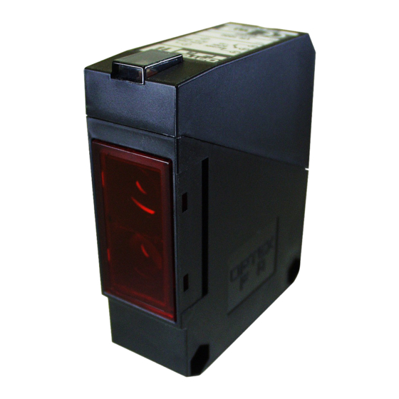
Photoelectric Sensor
V SERIES
AC/DC Type
DCAC/
Type
AC/DC Type
DC Type
・VT-4000□
・VT-3000□□
・VR-1000□
・VR-800□□
・VD-130□
・VD-100□□
・VD-300□
・VD-250□□
INSTRUCTION
MANUAL
Confirm if the item meets your needs.
Before the use, you should first thoroughly read
this manual and operate correctly as mentioned.
You should keep this manual at hand for proper use.
OTHER PRECAUTIONS
Be carefull not to install the sensor at the follwing locations,
as it may otherwise malfunction.
Where a lot of dust, vapor, or the like is present.
Where corrosive gas is produced.
Where water, oil or the like flies directly onto the sensor.
Where strong vibration or shock is caused to the sensor.
Do not use organic solvent, such as thinner, to remove
contaminants from the body case, lid, and lens which are all
of prastics. Using a dry rag, just wipe clean.
When a swiching regulator is to be used with a power supply,
be sure to ground the Frame Ground Terminal.
Do not use the sensor in a transient state at power on.(about
100ms)
Do not run sensor cable near a high-voltage lines, or power
lines or put them together in the same raceway. This warning
should be strictly observed to prevent malfuncdtions caused
by inductive interference.
Must not use this item as safety equipment
for the purpose of human body protection
INPUT AND OUTPUT CIRCUIT
DIAGRAMS
AC/DC type
DC type
NPN type
PNP type
DIMENSIONS
Ramco Innovations
(800) 280-6933 www.optex-ramco.com
For technical & application support or placing your order - contact Ramco today!
Through Beam
(with Polarizing filter)
without timer with timer without timer with timer without timer with timer without timer with timer
Terminal
VT-4000 VT-4000T VR-1000 VR-1000T VD-130
Type
M12
−
−
connector
Detecting distance
40m
Supply Voltage
DC12〜240V±10% AC24〜240V±10% 50/60Hz
Power/Current Consumption
8.5VA
Detecting Object
φ30mm
Response Time
Hysterisis
Light Source
Sensitivity Adjustment
Indicator
ON/OFF Delay
Timer function
−
0.1〜10sec
Operating Mode
Control Output
Relay output 1c AC240V 3A max./DC30V 3A max. (Resistive load)
Connection
Terminal base(Diameter of applicable cable:φ6〜φ10mm)
Ambient Temperature
Ambient Humidity
Environmental Illuminance
Insulation Resistor
Withstand Voltage
Vibration Resistance
Shock Resistance
Protection category
Material
NAME OF PARTS
AC/DC type
DC type
※Test Input function for through-beam
type is equipped to emitter.
TIMER CHART
Through beam emitter
Connector pin No.
AC/DC type
Retro Reflection
Diffused Reflection
Diffused Reflection
(Long Range type) Through Beam
VD-130T
VD-300
VD-300T
−
−
−
−
−
10m
1.3m
3m
5VA
φ50mm
□20cm
□40cm
20ms max.
−
20% max.
Red LED
IR LED
1 rotation volume(240°)
Output indicator (Orange) Power Indicator for Emitter (Red)
ON/OFF Delay
ON/OFF Delay
ON/OFF Delay
−
−
−
0.1〜10sec
0.1〜10sec
0.1〜10sec
Light ON
−25〜+55℃(No freezing)
35〜85%/RH
Sun Light:10,000lux max. Halogen light:3,000lux max.
20MΩ/DC500V
AC2700V 1 minute
10〜55Hz amplitude 1.5mm X.Y.Z.each 2 hours
50G(500m/s) X.Y.Z.each 2 hours
IEC144 IP67
Case/Cover:ABS(glass fiber Included) Lens:PMMA
HOW TO USE
Connection
Install the cables to match the connection terminal No. as
shown below.
Use either lead-in opening A or B according to the
installation method involved.
Install a vlinding bolt at the lead-in opening not to be used.
The figure below shows how the cables are installed when
lead-in opening A is used.
※1 Cable packing is selected separately either for cable or
blinding bolt according to cable diameter.
Large : φ8〜φ10 Small :φ6〜φ8
※2 Washer is to be used exclusively to the cable bolt.
DC type
Retro Reflection
Diffused Reflection
(with Polarizing filter)
VT-3000N
VR-800N
VD-100N
VT-3000P
VR-800P
VD-100P
VT-3000CN
VR-800CN
VD-100CN
−
VT-3000CP
VR-800CP
VD-100CP
30m
8m
DC10〜30V±10%
35mA max.
φ30mm
φ50mm
1.5ms max.
−
Red LED
−
Light ON/dark ON selectable by volume
NPN/PNP Open collector DC30V 100mA max.
Terminal base (Diameter of applicable cable:φ6〜φ10mm)/M12 Connector
−
Dimensions of applicable solderless terminals
3.2
Use solderless terminals with insulating tube.
Use 6 to 10 mm diameter cables circular in section to
maintain waterightness.
Wrong wiring may be a cause of burned or damaged sensor.
Pay due attention to wiring.
Be careful not to inslall the cable near power lines, for
otherwise the sensor may mulfunction.
Using the mounting accessories supplid, the sensor can be
installed on either floor or wall.
TEST INPUT FUNCTION
When the No. terminal is connected to 0V
Output ON
(NPN type) or 10〜30VDC (PNP type), an
Output OFF
interrupted status is electrically invented by
stoppage of emission. This function can be
used as the operational check of the sensor
b y e l e c t r i c i n t e r r u p t e d s t a t e w i t h o u t
detectable object.
ACCESORIES
Standard reflection mirror Type V-61
(for Retro-reflection model)
Specifications and equipment are subject to change
without any obligations on the part of manufacture.
For more information, questions and comments
regarding products, please contact us below.
Manufactured and sold by :
OPTEX FA CO.,LTD.
600-8815 Kyoto, Shimogyo, Awata Chudoji 93, Japan
T E L . +81− (0) 75−325−2920
FAX. +81− (0) 75−325−2921
Website : http//www.optex-fa.com
email us at nsales@ramcoi.com
Diffused Reflection
(Long Range type)
VD-250N
VD-250P
VD-250CN
VD-250CP
1m
2.5m
□20cm
□40cm
5ms max.
20% max.
IR LED
8
14
0550211
Advertisement
Table of Contents

Related Manuals for OPTEX FA V Series


Summary of Contents for OPTEX FA V Series
- Page 1 Photoelectric Sensor VT-3000N VR-800N VD-100N VD-250N Terminal VT-4000 VT-4000T VR-1000 VR-1000T VD-130 VD-130T VD-300 VD-300T VT-3000P VR-800P VD-100P VD-250P V SERIES AC/DC Type Type VT-3000CN VR-800CN VD-100CN VD-250CN − − − − − − − −...
- Page 2 仕様 AC/DC電源タイプ DC電源タイプ 回帰反射型 拡散反射型 透過型 拡散反射型 回帰反射型 拡散反射型 (変更フィルタ付) (長距離検出) 透過型 拡散反射型 (変更フィルタ付) (長距離検出) タイマ機能無 タイマ機能付 タイマ機能無 タイマ機能付 タイマ機能無 タイマ機能付 タイマ機能無 タイマ機能付 光電センサ VT-3000N VR-800N VD-100N VD-250N 端子台式 VT-4000 VT-4000T VR-1000 VR-1000T VD-130 VD-130T VD-300 VD-300T VT-3000P VR-800P VD-100P VD-250P 型式...
Need help?
Do you have a question about the V Series and is the answer not in the manual?
Questions and answers