Table of Contents
Advertisement
Quick Links
Advertisement
Table of Contents

Subscribe to Our Youtube Channel
Related Manuals for Dräger PSS Merlin


Summary of Contents for Dräger PSS Merlin
- Page 1 ® ® Dräger PSS Merlin Telemetry at your service Instructions for Use...
-
Page 3: Table Of Contents
Contents Contents For Your Safety ......4 In Use ........33 Definitions of Alert Icons . -
Page 4: For Your Safety
For Your Safety For Your Safety ® ® This instruction for use for the Dräger PSS Merlin Telemetry System must be used with the instructions for use supplied with the breathing apparatus (BA). Definitions of Alert Icons The following alert icons are used in this document to provide and highlight areas of the associated text that require greater awareness by the user. -
Page 5: Disposal Of Electrical And Electronic Equipment
For Your Safety Disposal of Electrical and Electronic Equipment Electrical and electronic equipment must not be disposed of as household waste. This is indicated by the adjacent symbol. The product can be returned to Dräger free of charge. For information please contact the national marketing organizations or Dräger. -
Page 6: Introduction
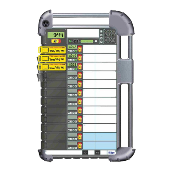
Introduction Introduction When the decision is taken to use self-contained respiratory protection apparatus (BA) in a life threatening hazardous environment, it is essential that an effective control procedure is in place to manage, monitor and safeguard the wearer of the equipment. In the United Kingdom, the Operational Guidance –... - Page 7 Introduction Entry Control Board ‒ Elements LCD Time Clock Display Screen Evacuation Button – All – Red 1436 LED Display – Distress Signal from non logged on device – Red 1437 LCD – Status Display Screen Information Button Default – Time of Whistle (TOW) or Time to Whistle (TTW) – Green LED Display –...
-
Page 8: Description And Intended Use
Description and Intended Use Description and Intended Use Electronic monitoring system An electronic monitoring system comprises a monitoring device paired with, or incorporating, a communication device. The monitoring device provides visual and audible information about the status of a breathing apparatus. The communication device transmits information from the monitoring device to compatible telemetry systems and other compatible devices, such as head- up displays. -
Page 9: Transmitting Information
Description and Intended Use ® Temperature of the monitoring system (Bodyguard II and Connect ECU only). By pressing the information button of the ECB, a controller is able to scroll between Time of Whistle, Time to Whistle, Pressure, and Temperature. The Time to Whistle information is the default data displayed on the electronic monitoring system. Additionally, the time elapsed from activating the electronic monitoring system to ‘operational mode’... -
Page 10: Getting Started
Getting Started Getting Started The Entry Control Board Power Supply The battery compartment at the rear of the Entry Control Board provides space for two 7.2 V rechargeable nickel hydride (NiMH) batteries each running in parallel and providing 3.8 Ah of power. Continuous operating time is a minimum of 8 hours between recharge. -
Page 11: Charging The Batteries
Getting Started Battery Compartment 1492 1 Battery 1 2 Battery 2 3 Gasket 4 Foam insert Charging the Batteries The Entry Control Board is supplied without the batteries charged or fitted. The batteries must be charged before initial use. A screw-lock connection plug is provided in the recess in the rear panel of the board to charge the batteries when they are assembled in the board. -
Page 12: Charging Procedure - Single Battery
Getting Started Charging Procedure – Single Battery Connect the plug adaptor of the charging lead to the battery. The green charge LED on the front panel of the battery will illuminate. When the LED begins flashing , this indicates: The battery is fully charged (approximately 14 hours for a fully depleted battery), or ... -
Page 13: In Use
In Use In Use An Entry Control Officer (ECO) is a competent person nominated to control and monitor an Entry Control Board (ECB) and to direct and instruct all wearers of breathing apparatus (BA) at an incident. A safe and secure entry control point (ECP) for the ECB should be established from which the ECO is able to effectively control the adopted procedures. - Page 14 In Use During the logon sequence the following visual changes take place on the ECB and the electronic monitoring system: 1. The channel screen momentarily displays the electronic monitoring system identification number, followed by the time elapsed count (E :00), then changes to the default Time of Whistle (TOW).
-
Page 15: Monitoring Data
In Use Making Contact ‒ Manual 5.2.2 An unsuccessful logon identified by an initial momentary display of the fault code (Et) followed by the display changing to E :00 (time elapsed count), indicates a probable defective transponder in the tally (a faulty tally must be reported and replaced as soon as possible). A single audible beep alarm is emitted until the manual logon is started. - Page 16 In Use 5.3.2 Time to Whistle Repeatedly press and release the information button until the status display shows TTW BG (Time to Whistle of the electronic monitoring system). All the active channel screens change to show the actual Time to Whistle status for each of the logged-on electronic monitoring system.
-
Page 17: Communication From Ecb To Electronic Monitoring System
In Use Communication from ECB to Electronic Monitoring System 5.4.1 Evacuation Signal – Selective This procedure allows the ECO to select and signal to a specific logged-on unit, or a designated number of units (team), to evacuate the risk area and return to the control point. ... -
Page 18: Communication From Electronic Monitoring System To Ecb
In Use Communication from Electronic Monitoring System to ECB 5.5.1 Voluntary Withdrawal Signal Should the wearer of the breathing apparatus make a decision to withdraw from an incident, a signal can be transmitted to the ECB by pressing and holding the RH button of the electronic monitoring system until the withdrawal request icon is displayed. -
Page 19: After Use
In Use 5.5.3 Distress Signal Unit (DSU) Manual Alarm – Panic Button Should the wearer of the breathing apparatus become distressed or require assistance then pressing the panic button activates the main audible alarm of the electronic monitoring system. The screen of the electronic monitoring system displays the manual distress alarm icon and a signal is transmitted to the ECB. - Page 20 In Use NOTICE The electronic monitoring system will remain in operating mode until it is switched off (deactivated). At the ECP the ECO identifies the wearer then removes the tally from the associated channel. The ECO records an exit dosimeter reading if necessary and hands the tally to the wearer.
- Page 21 In Use When the display shows LOGOFF, repeatedly press the key of the keypad to scroll the display until QUIT is displayed. When displayed, press the key – the display will change to show the date. If all electronic monitoring systems have been logged off, the ECB returns to sleep mode.
-
Page 22: Service Information
Service Information Service Information Setting Time Display NOTICE A single sharp audible beep signal sounds each time a key is pressed. With the ECB in sleep mode, press and then release the key of the keypad. The clock display and the status display will ... -
Page 23: Encoding A Tally
Service Information Encoding a Tally The following instruction details the procedure for encoding the transponder of a new tally with both equipment owner identification number (Brigade ID) and the electronic monitoring system identification number. This procedure can only be successfully activated with the tally inserted in the first channel (Channel 1) of the ECB. The equipment owner identification number (Brigade ID) is already encoded into the ECB and is automatically encoded on to the tally during the following procedure. -
Page 24: Removing/Fitting Battery Packs
Service Information Removing/Fitting Battery Packs 6.5.1 Entry Control Board Tools Required 3mm AF Hexagon Socket Key 3335737 Unscrew and remove the ten socket set screws from around the battery cover. When all screws have been removed, use fingers in the slots at the top and bottom of the back cover of the ECB to lift and remove the battery cover. -
Page 25: Troubleshooting
Troubleshooting Troubleshooting The troubleshooting guide shows fault diagnosis and repair information applicable to users of this product. Further troubleshooting and repair information is available in instructions for use supplied with associated equipment. Where the troubleshooting guide shows more than one fault or remedy, carry out repair actions in the order that they appear in the guide. -
Page 26: Merlin ® Modem (Bodyguard ® 7000 Only)
Troubleshooting Battery will not assemble to radio module Dirty dovetail guides Clean battery and radio module Damaged dovetail guides Inspect and replace damaged item Locking pins jammed Check action using release key Battery will not spring back (detach) on Broken pin(s) on release key. Use new key insertion of the release key Dirty dovetail guides... -
Page 27: Connect Ecu
Troubleshooting Connect ECU Symptom Fault Remedy Fault indication during the self-test or See Section 7.6.1 on Page 27 Note the fault code and contact service when switching off personnel or Dräger Loose or dirty connector Disconnect, clean and reconnect High-pressure leak test fail couplings and retest Faulty hose or component Substitute user replaceable accessories... -
Page 28: Technical Data
Technical Data Technical Data Operating Temperature Electronic monitoring system -32 °C to + 75 °C Control Board -15 °C to + 55 °C Storage Temperature Electronic monitoring system -15 °C to + 25 °C Control Board -15 °C to + 25 °C Telemetry Range 300 m (nominal) -
Page 29: Appendix A - Bodyguard ® Ii Portable Radio Unit
® Bodyguard II Portable Radio Unit ® Appendix A – Bodyguard II Portable Radio Unit IR Link/Battery Cover ® – Bodyguard Antenna Male Connector Female Connector Radio module Battery Tally Battery release key 1908 ® ® Dräger PSS Merlin... -
Page 30: Power Supply
® Bodyguard II Portable Radio Unit The Portable Radio Unit is a battery-powered unit incorporating an integral digital radio transmitter/receiver with associated ® antenna. A cable and connector from a radio module connects to an infrared (IR) Link Unit on the Bodyguard . -
Page 31: In Use
® Bodyguard II Portable Radio Unit There is a battery fault condition. Contact Dräger if a fault condition is suspected. A flashing green LED indicates a full charge. Remove the battery and assemble the battery to the Portable Radio Unit. -
Page 32: Appendix B - Bodyguard ® 7000 Pss ® Merlin ® Modem
® ® ® Bodyguard 7000 PSS Merlin Modem ® ® ® Appendix B – Bodyguard 7000 PSS Merlin Modem ® ® Merlin Modem Antenna Tally 2989 ® ® The PSS Merlin Modem is a battery-powered unit incorporating an integral digital radio transmitter/receiver with an external antenna. ®... -
Page 33: In Use
® ® ® Bodyguard 7000 PSS Merlin Modem In Use ® B.2.1 Radio Contact (Entry Control Board – Merlin Modem) When the tally is inserted into any of the available channels of the Entry Control Board, the ® ® ECB identifies the associated Merlin Modem/Bodyguard combination and the digital communication link is activated (logon). -
Page 34: Battery Pack
® ® ® Bodyguard 7000 PSS Merlin Modem Battery pack B.3.1 General WARNING ® ® Do not fit the Merlin rechargeable battery pack to a breathing apparatus that is not fitted with a Merlin Modem. Exposed battery terminals may cause a risk of explosion or fire through sparking. NOTICE Rechargeable batteries are supplied fully discharged. - Page 35 ® ® ® Bodyguard 7000 PSS Merlin Modem Whilst pushing down, confirm the two sliding locks move to their locked position viewed through the two keyholes as shown. Tighten (nip up) the screw using a suitable coin until it bottoms in the recess and a noticeable increase in turning force is felt (do not over tighten or damage will occur).
- Page 36 ® ® ® Bodyguard 7000 PSS Merlin Modem B.3.7 Battery LED The bi-colour LED (orange and green) on the battery shows the status of the battery during charging. 2997 Battery LED Status Action Green Maintenance charge – battery sufficiently charged Leave on charge Charging–...
- Page 37 ® ® ® Bodyguard 7000 PSS Merlin Modem Charging error 1 The radial segments could show any battery charge state. 2 The battery error icon is displayed. Notes: If the LED on the battery pack is green, the battery pack is sufficiently charged. For remedy actions for the charging error see Note 1 on Page 36.
-
Page 38: Appendix C - Appendix C - Pss ® Airboss Connect
® Appendix C – PSS AirBoss Connect ® Appendix C – Appendix C – PSS AirBoss Connect The Dräger Connect ECU is a battery powered integrated electronic monitoring system used on Dräger breathing apparatus. The system provides visual and audible information about the status of the breathing apparatus, and has an integral DSU. Visual information is provided on the LCD screen, and by LEDs in the LED panel of the Connect ECU UI module and in the buddy beacons in the backplate. -
Page 39: Appendix D - Manual Operation Of Ecb
Manual Operation of ECB Appendix D – Manual Operation of ECB ® ® As outlined in the introduction section of this Instruction for Use, the Dräger PSS Merlin Entry Control Board (ECB) provides a means of remote two-way digital data and alert status communication between the ECB and electronic monitoring system on breathing apparatus. -
Page 40: After Use
Manual Operation of ECB Refer to the appropriate Working Duration table to establish the remaining time (in WORKING DURATION minutes) available to the wearer. This can be interpreted and recorded as either: BASED ON 55 BAR WHISTLE SETTING AT 40 L/MIN BREATHING RATE 6.8 L 300 Bar A time elapsed to whistle activation. -
Page 41: Appendix E - Propagation
Propagation Appendix E – Propagation The signal power of a radio frequency transmission diminishes over distance. Signal power will also decrease in strength as the radio wave passes through solid objects such as terrain, trees, walls, windows and the floors of buildings, storage tanks, underground (tunnels), etc. - Page 42 Propagation To maximise propagation of the transmitted radio signal at an incident, the antenna of the ECB should be positioned as high as possible above the ground to minimise transmission losses that may be caused by objects on the ground and also to reduce the effects of radio waves reflected from the ground.
-
Page 43: Enhancing Transmission
Propagation Enhancing Transmission E.2.1 Repeaters As outlined in the preceding sections, the critical factor influencing the maintenance of positive radio contact is the location of the antennas. There are some instances where an RF propagation problem could result in some, or all, of the electronic monitoring units losing radio contact and becoming unable to communicate directly with the ECB. - Page 44 Propagation Possible locations for Repeaters are inside the entrance of a building, at the top of basement stairs, the bottom of stairs, at the entrance to, or at a sharp corner in a corridor or tunnel, etc. In reality, as illustrated, the actual spread of the radio signal may mean that the optimum position may be at some point further down the stairs, or in the case of a tunnel, further into the entrance.
-
Page 45: Customer Evaluation Trials
Propagation The following illustrations show two possible system layouts. For clarity the coaxial cable is shown coiled on the winding reels but for operation the cable would be fully unwound from the reel. Single Repeater 2852 Two Repeaters 2853 Refer to the Instructions for Use provided with the Repeaters and Leaky Feeders for full details. Customer Evaluation Trials It is important to be aware that radio communication can be affected by a breakdown in the transmission signal due to extremes of application such as long distances, building construction, below ground structures, etc. -
Page 46: Appendix F - Additional Entry Control Board Functions
Additional Entry Control Board Functions Appendix F – Additional Entry Control Board Functions ® ® The additional functions listed and described below can be configured and used on the Dräger PSS Merlin Entry Control Board (contact Dräger for full details). Retreat alert ... - Page 47 Additional Entry Control Board Functions F.1.1 Early Retreat The breathing apparatus wearer can activate an early retreat at the electronic monitoring system by cancelling the retreat alert before the retreat pressure is reached. If an early retreat is activated at the electronic monitoring system, the following indications occur on the Entry Control Board: The red LED above the channel evacuation button illuminates.
- Page 48 Additional Entry Control Board Functions F.1.3 Mission Status Repeatedly press and release the information button until the status 2510 display shows STATUS. All active channel screens change to show the mission status of the associated breathing apparatus (see the chart above for status descriptions and mission progress).
-
Page 49: Personal Tally
Additional Entry Control Board Functions Personal Tally A personal tally can be programmed with data that identifies a specific breathing apparatus wearer. The tally can also be programmed with a countdown time. The full data that can be programmed on to the tally is: Name Up to 12 characters (up to 17 if organization is left blank) ... -
Page 50: Serial Number Tally
Additional Entry Control Board Functions When the countdown time reaches zero, a single double-beep sounds and 0 appears on the channel screen. The timer continues and negative time is displayed until the tally is removed. 2488 F.2.3 Changing the Countdown Time At any time after inserting the personal tally, press and hold the channel evacuation ... -
Page 51: Team Operation
Additional Entry Control Board Functions Team Operation Entry Control Board channel slots can be linked to form fixed teams. The size of each team is decided at the time of order and configured during the factory commissioning process (contact Dräger for details). F.5.1 Use with Telemetry If a selective evacuation signal (see Evacuation Signal –... -
Page 52: Bs 8608 Operation
Additional Entry Control Board Functions BS 8608 Operation This section describes system functionality when BS 8608 (Specification for radio telemetry systems for use with respiratory ® ® protective devices used by emergency first responders) is enabled. BS 8608 can be enabled on Dräger PSS Merlin telemetry systems which use the 469.9 MHz ECB. - Page 54 Dräger Safety UK Limited Ullswater Close Blyth, NE24 4RG United Kingdom Tel +44 1670 352 891 Fax +44 1670 356 266 www.draeger.com 3351236 © Dräger Safety UK Limited Edition 30 – 2023-12 Subject to alteration...
Need help?
Do you have a question about the PSS Merlin and is the answer not in the manual?
Questions and answers