
Subscribe to Our Youtube Channel
Related Manuals for TKR Group 83 30 5 A40 812

Summary of Contents for TKR Group 83 30 5 A40 812
- Page 1 83 30 5 A40 812 83 30 5 A40 810 83 30 5 A40 809 83 30 5 A40 808 83 30 5 A40 814 83 30 5 A40 C20 RADAR calibration tool (RCT) Translation of the original owner‘s manual...
- Page 2 Owner‘s Manual USB-Stick www.tkr-service.com 83 30 5 A40 812 83 30 5 A40 810 83 30 5 A40 809 83 30 5 A40 808 83 30 5 A40 814 83 30 5 A40 C20 RADAR-Kalibriergerät (RCT) Originalbetriebsanleitung Owner‘s manual, Owner‘s manual,...
-
Page 3: Table Of Contents
Safety Application General instructions Operating the control Explanation of symbols Software Update Designations Adjustment of the vehicle / the RADAR System components calibration tool (RCT) to each other Safety instructions Calibration of the sensors Putting out of operation and storage Technical Data Maintenance Rail set (RCT) -
Page 4: General Instructions
1.1 General instructions State-of-the-art Declaration of Conformity This tool is state-of-the-art technology. To ensure that the The tool has been manufactured and inspected in equipment operates safely, it must be operated in a proper and compliance with International directives. The Decla- safety-conscious manner. -
Page 5: Explanation Of Symbols
Arrow to clarify compression Hands could become trapped Warning! For more information, see Sharp object Chapter … 1.3 Designations RADAR-Kalibriergerät (RCT) 83 30 5 A40 812 Serien-Nr.: 0250 10/22 ⎓ Input: 12 V 1,0 A TKR Spezialwerkzeuge GmbH Am Waldesrand 9-11, D-58285 Gevelsberg Manufacturer’s label... -
Page 6: System Components
1.4 System components 83 30 5 A40 810 83 30 5 A40 812 3.5.2 Assembly 3.4.2 Assembly 3.5.3 Battery change 83 30 5 A40 809 83 30 5 A40 808 3.7.2 Battery change 83 30 5 A40 814 83 30 5 A40 C20 ... -
Page 7: Safety Instructions
1.5 Safety instructions CAUTION CAUTION If used with the wrong accessories, this may cause Risk of personal injury material damage and bodily injury. To protect against electric shock, make sure the Not using original tools and original accessories will tool is not connected to the power supply before result in a high risk to safety. -
Page 8: Technical Data
2.1 Rail set (RCT) Technical Data 83 30 5 A40 810 3000 83 30 5 A40 810 Rail set (RCT) Type of device 83 30 5 A40 810 Rail set (RCT) Ambient temperature (operation) 0 °C to +50 °C / +32 °F to +122 °F Ambient temperature (storage) -20 °C to +60 °C / -4 °F to +140 °F Ambient humidity... -
Page 9: Radar Calibration Tool (Rct)
2.2 RADAR calibration tool (RCT) Technical Data 83 30 5 A40 812 83 30 5 A40 812 RADAR calibration tool (RCT) Type of device 83 30 5 A40 812 RADAR calibration tool (RCT) Ambient temperature (operation) 0 °C to +50 °C / +32 °F to +122 °F Ambient temperature (storage) -20 °C to +60 °C / -4 °F to +140 °F... -
Page 10: Slotted) Cover
2.3 (Slotted) Cover Technical Data 83 30 5 A40 809 83 30 5 A40 809 (Slotted) Cover Type of device 83 30 5 A40 809 (Slotted) Cover Ambient temperature (operation) 0 °C to +50 °C / +32 °F to +122 °F Ambient temperature (storage) -20 °C to +60 °C / -4 °F to +140 °F Ambient humidity... -
Page 11: Wheel) Laser
2.4 (Wheel) Laser Technical Data 83 30 5 A40 808 83 30 5 A40 808 (Wheel) Laser Type of device 83 30 5 A40 808 (Wheel) Laser Ambient temperature (operation) 0 °C to +50 °C / +32 °F to +122 °F Ambient temperature (storage) -20 °C to +60 °C / -4 °F to +140 °F Ambient humidity... -
Page 12: Side Panel Absorber
2.5 Side panel absorber Technical Data 83 30 5 A40 814 83 30 5 A40 814 Side panel absober (RCT) Type of device 83 30 5 A40 814 Side panel absober (RCT) Ambient temperature (operation) 0 °C to +50 °C / +32 °F to +122 °F Ambient temperature (storage) -20 °C to +60 °C / -4 °F to +140 °F Ambient humidity... -
Page 13: Extension For Side Panel Absorber
2.6 Extension for Side panel absorber Technical Data 83 30 5 A40 C20 83 30 5 A40 C20 Extension for Side panel absorber Type of device 83 30 5 A40 C20 Extension for Side panel absorber Ambient temperature (operation) 0 °C to +50 °C / +32 °F to +122 °F Ambient temperature (storage) -20 °C to +60 °C / -4 °F to +140 °F Ambient humidity... -
Page 14: Intended Use
3.1 Intended use The RADAR calibration tool (RCT) is a tool for calibrating the The application is described in the diagnostic device (ISTA). radar sensors in the vehicle. The motor system of the RADAR cali- All parameters of the tool necessary for safe use are specified by bration tool (RCT) specifies various settings to which the vehicle the diagnostic device (ISTA). -
Page 15: Assembly
3.3 Commissioning and safe handling CAUTION Protect the tool from moisture, humidity and con- Risk of injury densation. Avoid using liquids of any kind in the Lay all supply cables so that they cannot be damaged proximity of the tool. These can get into the tool. and nobody can trip over them. - Page 16 3.4 Rail set (RCT) 3.4.1 Scope of delivery 83 30 5 A40 810 83 30 5 A40 810 - Rail set (RCT) Article Pieces Drilling template incl. cap screws Washer Headless pin, M6x8 Headless pin, M6x12 Headless pin, M6x16 Panhead screw with flange, M6x16 Panhead screw with flange, M6x20 Panhead screw with flange, M6x25 Expansion dowel...
-
Page 17: Assembly
When not in use, the radar calibration device (RCT) remains in a parking + Level position on the rails. + Profile 683 mm The system can be extended if required: (83 30 5 A40 812 5.3 Spare parts and accessories RADAR calibration tool (RCT)) ... - Page 18 Then remove the drilling template. When using the profile 683 mm (from 83 30 5 A40 812 RADAR calibration tool (RCT) as an aid, it must be placed directly against the inner edge of the rail segments for alignment. If necessary, remove the cover cap first.
- Page 19 Fig. 3 Fig. 4 Fig. 3 Fig. 4 Pre-assemble rail segments Levelling the rail segments Drive expansion dowels into the holes with a hammer and Position the levelling device (e.g. level, (Wheel) Laser) on the rail then anchor them with a punch/splint driver and a hammer. segment and level the rail segments with the headless pins.
- Page 20 Fig. 5 Fig. 5 Backfilling the levelled rail system: Before backfilling, cover the area around the rail segments and the workshop floor with protective tape. Observe the processing instructions of the used adhesive. Spray the free space between the lower edge of the rail seg- ments and the workshop floor with a suitable one-component polymer adhesive.
- Page 21 07-00001693 Senkschraube ISO 10642 - M5 x 16 Senkschraube ISO 10642 - M8 x 30 Gewindestift ISO 4027 - M8 x 10 83 30 5 A40 812 - RADAR calibration tool (RCT) Pos. Article Pieces Measuring tape, 0-2000 mm (self-adhesive)
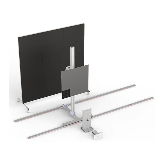
- Page 22 3.5 RADAR calibration tool (RCT) 3.5.2 Assembly 83 30 5 A40 812 Illustration of fully assembled RADAR calibration tool (RCT) Tools required for assembly: The RADAR calibration tool (RCT) is positioned on the Rail set (RCT) in order + Allen wrench...
- Page 23 The item numbers in the pictures refer to the number range shown in the scope of delivery ( 3.5.1). Fig. 1 Fig. 2 Fig. 1 Fig. 2 Preparing the assembly of the RCT module Preparing the assembly of the RCT module 2 persons are required for assembly.
- Page 24 Fig. 3 Fig. 4 Fig. 3 Fig. 4 Attaching the safety belt Preparing the roller carriage Put the clamping plate with countersink [15] through the loop of Place the profile 870 mm [18] on the roller carriage [17] and fas- the safety belt and tighten it firmly with the two countersunk ten it from below with the countersunk screw [19].
- Page 25 Fig. 6 Fig. 6 Fastening the securing strap Pull the securing strap smoothly downwards. Stack the two clamping plates [21] and screw them loosely to the profile with the two socket head screws [22]. Guide the safety belt through the two plates, tighten it and fix it with the socket head screws [22].
- Page 26 Fig. 7 Fig. 8 Fig. 7 Fig. 8 Calibrating RADAR calibration tool (RCT) Attaching the measuring tape to the profile 2 persons are required for assembly. Before finally attaching the measuring tape to the profile, determine the exact position. To set up the RADAR calibration tool (RCT), all previous assembly steps from Figures 1 - 6 must Attach the tape measure so that the position of be completed.
- Page 27 3.5 RADAR calibration tool (RCT) 3.5.3 Battery change: Remote control Fig. 1 Fig. 1 Battery change remote control To change the battery, turn the remote control over. Remove the batteries from the remote control if it Open and remove the battery compartment cover on the back. will not be used for a long time.
- Page 28 3.5 RADAR calibration tool (RCT) 3.5.4 Battery change: Control Fig. 1 Fig. 2 Fig. 1 Fig. 2 Disassembling the RCT module (control unit) Disassembling the RCT module (control unit) The real-time clock of the control unit is buffered by a battery on Put the cover plate aside.
- Page 29 Fig. 3 Mounting the RCT module (control unit) For assembly, place the cover plate and the circuit board on top of each other and push them together into the housing of the control unit. Put on the cover and base and mount them with the 8 Screws placed to one side.
- Page 30 3.6 (Slotted) Cover 3.6.1 Scope of delivery 83 30 5 A40 809 83 30 5 A40 809 - (Slotted) Cover Article Piece (Slotted) Cover Illustration of fully assembled (Slotted) Cover The (Slotted) Cover is placed between the (Wheel) Laser and the RADAR calibration tool (RCT) and is used for the correct vertical alignment of the calibration mirror.
- Page 31 3.7 (Wheel) Laser 3.7.1 Scope of delivery 83 30 5 A40 808 83 30 5 A40 808 - (Wheel) Laser Article Piece (Wheel) Laser Illustration of fully assembled (Wheel) Laser The (Slotted) Cover is placed between the (Wheel) Laser and the RADAR calibration tool (RCT) and is used for correct horizontal and vertical alignment of the calibration mirror.
- Page 32 3.7 (Wheel) Laser 3.7.2 Battery change Fig. 1 Fig. 2 Fig. 1, Fig. 2: Battery change To change the batteries, switch off the (Wheel) Laser. Open the Remove the batteries from the (Wheel) Laser if it will not be used for a long time. battery compartment cover on the side and remove it.
- Page 33 3.8 Side panel absorber 3.8.1 Scope of delivery 83 30 5 A40 814 83 30 5 A40 814 - Side panel absorber Accessories for side extension Pos. Article Pieces Profile, 1000 mm, left and right Profile, 720 mm Connector, profile extension Connector, standard Roller carriage Absorber panel, 500x1000 mm...
- Page 34 3.8 Side panel absorber 3.8.2 Assembly 83 30 5 A40 814 Fig. incl. additional side panel absorber top (RCT): 83 30 5 A40 C20 Illustration of fully assembled Side panel absorber Tools required for assembly: + Allen key 2.5 mm, 5 mm The Side panel absorber is set up according to the instructions of the diag- nostic device (ISTA).
- Page 35 The item numbers in the pictures refer to the number range shown in the scope of delivery ( 3.8.1). Fig. 1 Fig. 2 36 36 36 36 Fig. 1 Fig. 2 Connecting profiles for lower frame Assembling the lower frame [28] [36] Disassemble the "profile extension"...
- Page 36 Fig. 4 Fig. 4 Connecting the frame Assemble and mount frame parts in the laid- Insert the already assembled lower frame with the "Standard" down position. [29] connectors into the two prepared side profiles. Make sure that the threaded plates in the side profiles are below. 2 persons are required for assembly.
- Page 37 Fig. 5 Fig. 5 Inserting absorber elements 2 persons are required for installation. Raise the frame and tilt it slightly. First insert the side absorber plates [31] on the left and right. Finally insert the middle absorb- Do not contaminate or damage the absorber ma- er plate [32].
- Page 38 Fig. 7 Fig. 8 Fig. 8, Fig. 9 Protect absorber elements 2 persons are required for installation. Absorber elements must not become dirty. Oth- erwise interfering radiation can affect the meas- urement. [33] Pull the protective cover over the finished movable panel so that the holes in the upper frame through the ring eyelets at the top left and right remain free.
- Page 39 3.9 Extension for Side panel absorber 3.9.1 Scope of delivery 83 30 5 A40 C20 83 30 5 A40 C20 - Extension for Side panel absorber Pos. Article Pieces Profile, 500 mm, left and right Profile, 720 mm Connector, profile extension Connector, standard Absorber panel, 500x500 mm Absorber panel, 500x1000 mm...
- Page 40 3.9 Extension for Side panel absorber 3.9.2 Assembly 83 30 5 A40 C20 Fig. incl. Side panel absorber : 83 30 5 A40 814 Illustration of fully assembled Extension for Side panel absorber Tools required for assembly: + Allen key 2.5 mm, 5 mm The Side panel absorber is set up according to the instructions of the diag- nostic device (ISTA).
- Page 41 The item numbers in the pictures refer to the number range shown in the scope of delivery ( 3.9.1). Fig. 1 Fig. 2 Fig. 1 Fig. 2 Assembling the upper and lower frames Fitting the side frames Dismantle the "profile extension" connector [43] and insert the Prepare the "Standard"...
- Page 42 Fig. 4 Fig. 5 Fig. 4 Fig. 5, Fig. 6 Inserting absorber elements Assembling protected absorber elements 2 persons are required for installation. Absorber elements must not become dirty. Other- wise, interfering radiation can affect the measure- Do not contaminate or damage the absorber ma- ment.
- Page 43 4.1 Operating the control 83 30 5 A40 812 – Control 83 30 5 A40 812 - RADAR calibration tool (RCT), Control Pos. Title Control Remote control Power button – Function key 1 Function key 2 Function key 3 –...
- Page 44 The item numbers in the pictures refer to the number range shown in this chapter ( 4.1). Fig. 1 Fig. 2 Fig. 1 Fig. 2 Self-diagnosis Navigation and operation When starting the RADAR calibration tool (RCT) via the power After successful self-diagnosis, the main menu of the control key [49] of the control, a self-diagnosis is carried out automat- opens.
- Page 45 Fig. 3 Fig. 5 Fig. 4 Fig. 6 Fig. 3, Fig. 4 Fig. 5, Fig. 6 Operation SetUp Menu [56] Operation Parameter menu [59] For the basic setting of the calibration mirror, If "no IR" appears in the display, control via observe the corresponding repair instructions the remote control is not intended.
- Page 46 You will find current information in our customer service area: www.tkrgroup.com/service-faq Fig. 7 Fig. 8 Fig. 7 Fig. 8 Operation Calibration mode: 3-POS [57] Operation Calibration mode: 10-POS [58] For the basic setting of the calibration mirror, For the basic setting of the calibration mirror, observe the corresponding repair instructions observe the corresponding repair instructions for the respective vehicle model.
- Page 47 4.2 Software Update Fig. 1 Information on the current firmware version can be found in the parameter menu [59] of the control. CAUTION Risk of damage to the tool The designation and content of the update files must not be changed. This may cause damage to the unit. Fig.
- Page 48 The item numbers in the pictures refer to the number range shown in this chapter ( 4.2). Fig. 2 Field Value System updates must only be carried out by au- Connect thorised personnel. Port E.g. COM4 Baud 115200 The system update may take several minutes; do Data not disconnect the tool from the power supply Stop...
- Page 49 Fig. 3 Fig. 4 Fig. 3 Fig. 4 Selecting firmware update in the control unit Unlocking the update function in the control unit [59] [56] Open the Parameter menu in the SetUp Menu of the To receive the update file, select "YES" via the navigation keys control unit.
- Page 50 You will find current information in our customer service area: www.tkrgroup.com/service-faq Fig. 7 Fig. 8 Fig. 7 Fig. 8 Activating the boot loader Running the update [50] [54] When plugging in the power supply, keep function key 1 Pressing the Enter key starts the update.
- Page 51 + 83 30 2 338 466 3.1 to 3.9 Magnetic wheel holder + 83 30 5 A40 812 At each start-up, the system performs a self-di- RADAR calibration tool (RCT) agnosis. This process may take a few minutes. + 83 30 5 A40 810 Rail set (RCT)
- Page 52 You will find current information in our customer service area: www.tkrgroup.com/service-faq Fig. 1 Fig. 3 Fig. 2 Fig. 3 Adjusting the (Slotted) Cover Mount the magnetic wheel holder on the rear wheel to cali- brate the front sensors, and mount it on the front wheel to cali- brate the rear sensors.
- Page 53 Fig. 5 Fig. 6 Fig. 5 Abb. 7 Aligning the calibration mirror The calibration mirror must be aligned at right angles to the ve- hicle's driving axis. To do this, position the (Slotted) Cover in front of the rail system. Adjust the calibration mirror so that the (Wheel) Laser beam falls through the slit in the (Slotted) Cover onto the calibration mirror behind it.
- Page 54 4.4 Calibration of the sensors Fig. 8 Fig. 9 300 mm 300 mm 300 mm 300 mm Fig. 8, Fig. 9 Detection range There must be no objects in the detection range for calibration. The calibration mirror must always be positioned centrally in front of the respective sensors to be calibrated.
- Page 55 Fig. 10 Fig. 11 Fig. 10 Fig. 11 Calibration mirror alignment to calibrate the sensors Centring the RADAR calibration device (RCT) [24] Set (Slotted) Cover aside. Remove (Wheel) Laser and magnetic Place the measuring tape 1000-0-1000 mm directly against wheel holder. the front rail and push it so that the zero is exactly in the centre mark of the roller carriage.
- Page 56 Fig. 12 Fig. 13 Fig. 12, Fig. 13 Setting up the absorber screen The absorber screen prevents the spread of inter- During the calibration process, it is necessary to seal off the de- fering radiation that can influence the calibration. tection range against unwanted interference and reflections us- ing the absorber screen.
- Page 57 Carry out calibration of the sensors Fig. 15 For the basic setting of the calibration mirror, ob- serve the repair instructions of the respective ve- hicle model. For the selection of the correct calibration mode, observe the corresponding repair instructions of the respective vehicle model.
- Page 58 4.5 Putting out of operation and storage Caution: Glass! covers to protect the sensitive surface of the absorber material Risk of breakage. Do not bump. from contamination. If the tool is no longer used, disconnect it completely from For storage, slide the RADAR calibration tool (RCT) into a parking the power circuit by pulling out the mains plug.
- Page 59 5.2 Troubleshooting Malfunction Possible cause Solution Chapter Replace empty batteries with new The batteries of the remote control are The remote control does not work ones and press the button at the top 3.5.3 empty right Press the button at the top right: The remote control does not work Remote control not properly adjusted Function key 3 [52]...
- Page 60 5.3 Spare parts and accessories RADAR calibration tool (RCT), 83 30 5 A40 812 Partial refer- Designation Pieces Art. no. Art. no. ence path 83 30 5 A40 812 WZS-BMW-00000280 RADAR calibration tool (RCT) incl. owner's manual BGR-BMW-00001833 Calibration mirror (RCT)
- Page 61 6.1 Disposal Devices and machinery and components of devices and machinery must be disposed of in compliance with the laws, regulations and other stipulations of the country in which they are located. We recommend using specialist licensed companies for disposal. The modules and units have been developed to be environmentally compatible and suitable for recycling.
- Page 62 Thorsten Weyland Type of Tool: Measuring System / RADAR calibration tool (RCT) Type designation: 83 30 5 A40 812 The product is developed and constructed in accordance with the UK legislation and designated standards. Applicable UK legislation: Electrical Equipment (Safety) Regulations 2016...
- Page 63 Thorsten Weyland Tool type: Measuring System / RADAR calibration tool (RCT) Type designation: 83 30 5 A40 812 Developed and constructed in accordance with the standards and guidelines stated below, by TKR Spezialwerkzeuge GmbH Am Waldesrand 9–11...
- Page 64 Am Waldesrand 9–11 D-58285 Gevelsberg (Germany) Other languages, accessories and Telefon +49 2332 66607-0 Telefax +49 2332 66607-941 spare parts: www.tkr-service.com E-Mail info@tkrgroup.com Internet www.tkrgroup.com...
Need help?
Do you have a question about the 83 30 5 A40 812 and is the answer not in the manual?
Questions and answers